The antenna design and dimensions are taken from Example 6-2 on page 239 of “Antenna Theory and Design” by Stutzman and Thiele [1]. The center frequency is 8 GHz giving a helix circumference of 3.45 cm. The helix is constructed with a right hand (clockwise) twist to produce a right hand circularly polarized far-field pattern. The spacing between turns is 0.796 cm. The theoretical half-power beam width of 44 degrees and 39 degrees is provided in Figure 6-14a and 6-14c [1]. These two beam widths represent a value taken from measurements and computed from simple theory.
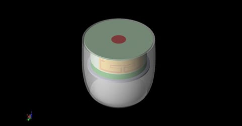
The antenna is constructed in XFdtd using the helix script. The helix will expand along the Z-axis and will have a radius of 0.549 cm. In addition to the helix, a small 2D ground plane is centered on the base of the helix with dimensions of 4 cm x 4 cm. The resulting CAD model geometry is shown in Figure 1. It was meshed with a cubical cell size of 0.3 mm.
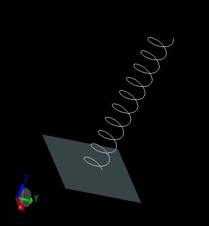
Figure 1: CAD model of helix.
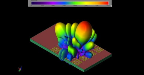
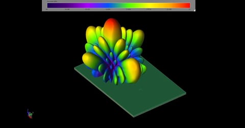
The feed is applied to the cell edge that connects the helix to the base plate. A sinusoidal signal at 8 GHz is used as the waveform, and automatic convergence criteria is set to -30 dB. Following the simulation, the far zone patterns are computed in a 2D cutplane and as a 3D pattern. The right hand circularly polarized pattern is shown in Figure 2. Since the antenna is right polarized, the left hand polarization pattern, shown in Figure 3, is much lower.
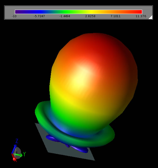
Figure 2: Right hand circularly polarized far zone gain pattern.
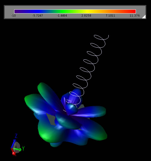
Figure 3: Left had circularly polarized far zone gain pattern.
The gain of the main beam is plotted in a two-dimensional line plot to determine the half-power beam width. The plot in Figure 4 indicates a half power beam width of approximately 42.5 degrees which falls between the two values provided by Stutzman and Thiele. Figure 5 is the full 2D slice at phi = 0 degrees.
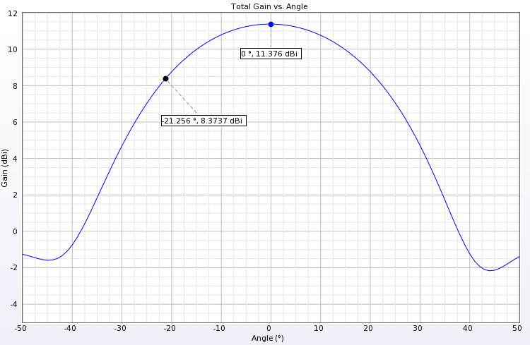
Figure 4: Half power beam width.
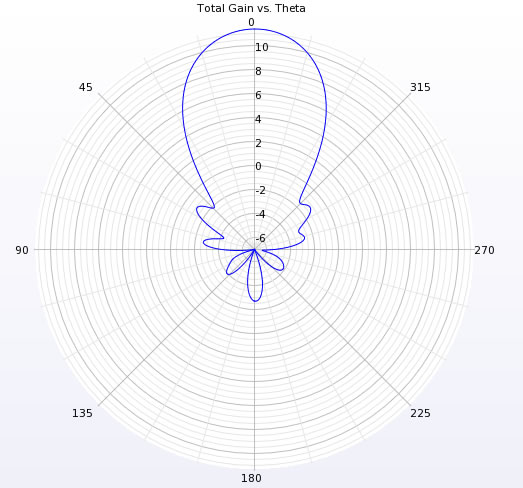
Figure 5: Total gain at phi = 0 degrees.
Reference
-
Stutzman and Thiele. Antenna Theory and Design. 2nd ed. New York: John Wiley and Sons, 1998.