An evaluation of the changes in performance such as radiation pattern, return loss, impedance and efficiency of a simplified cellular telephone worn on the hip of a detailed man model is performed in this example. The telephone used is a fictitious flip phone in the closed position which consists primarily of a ground board with a triple band antenna tuned to provide low return loss at 1.9 GHz. The human model is based on the Visible Human Project male and is described by a 5mm cubical mesh with material parameters adjusted for 1.9 GHz. The human model is placed in several poses, first to simulate a walking man, and then to show the impact of various arm positions on the telephone.
The simplified cellular phone is positioned on the right hip of the body to emulate a belt-mounted situation where the phone does not contact the skin of the body, as shown in Figure 1. Due to the detailed nature of the phone, a much finer resolution of the FDTD mesh is required than the 5mm used for the body. Detailed mesh regions as small at 0.1667 mm are used to ensure well-defined resolution the phone. The software product VariPose is then used to reposition the limbs of the body into the different positions and the field simulations are performed using XFdtd.
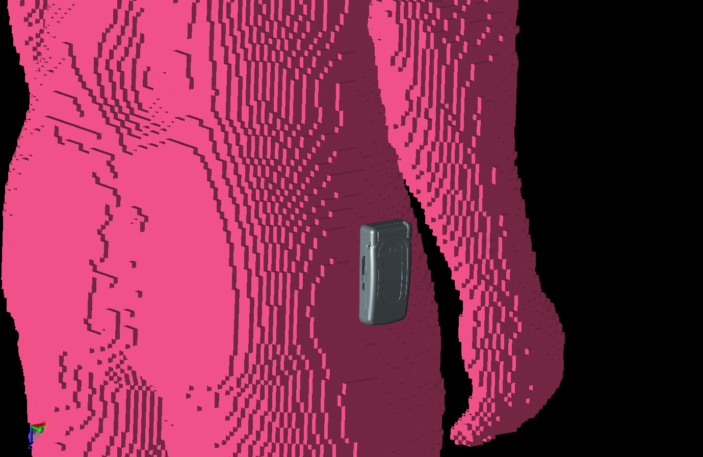
Figure 1: Shown is the hip-worn cellular telephone shown in grey next to the VariPose human male body mesh.
As a first example, the man is repositioned into three walking poses where the arms and legs are positioned for a step with the left and right foot forward with a neutral position in between. The first position with the left foot forward is shown in Figure 2, and the neutral and right foot step positions are shown in Figures 3 and 4. In all cases, the phone remains suspended in space and does not touch the hip or arm, but as can be seen, the arm does come close to the phone in two of the poses. In position 1 (Figure 5), the right arm is forward of the phone and the radiation pattern produced by the phone shows highest gain to the right side of the body.
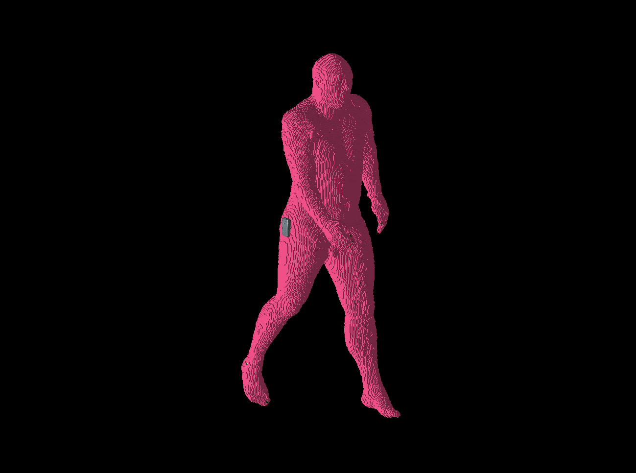
Figure 2: Position 1 of the walking man is shown with the left foot forward and the right arm forward of the phone location.
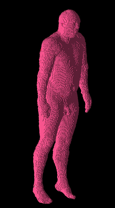
Figure 3: Position 2 of the walking man is shown where the man is in a neutral position with neither leg forward and the arms hanging down at the sides.
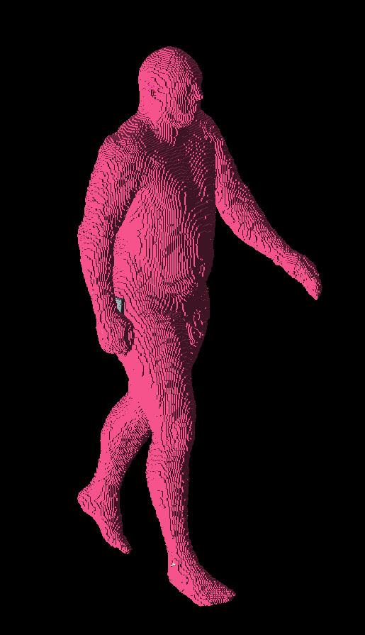
Figure 4: Position 3 of the walking man is shown where the right foot is forward and the right arm is back but still covering much of the phone.
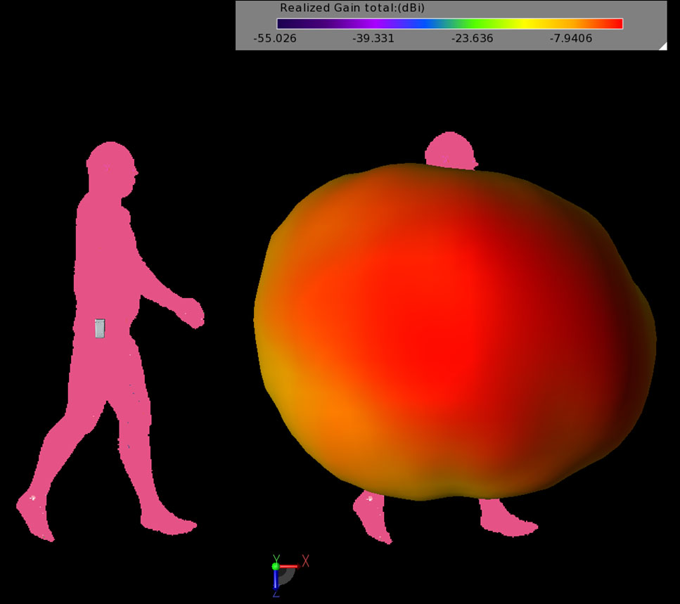
Figure 5: The gain pattern for walking man Position 1 where the gain pattern is strongest to the side of the body.
As the right arm moves back to be closer to the phone position in Positions 2 and 3 (Figures 6 and 7), the gain from the antenna decreases and is directed toward the forward and reverse directions. The return loss and impedance show little impact from the different body positions; however, the efficiency drops significantly for the two cases where the arm is close to the phone as shown in Table 1. The gain plots for all three positions are plotted together for the horizontal case (Figure 8) and the vertical case (Figure 9) where the vertical slice is through right-to-left cross section of the body. In Figure 8, the body is facing toward 0 degrees and the phone is at 90 degrees. In Figure 9, the hip with the phone is again at 90 degrees.
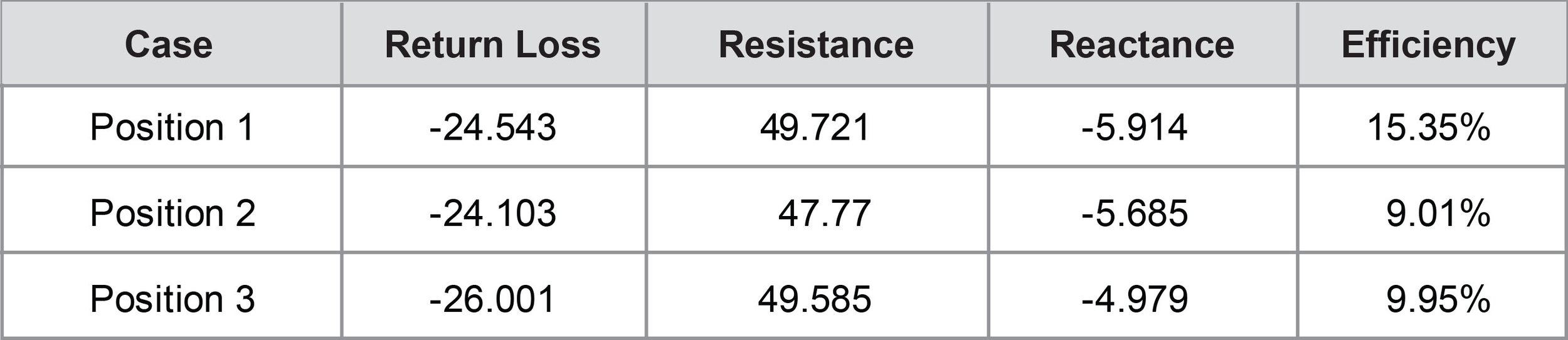
Table 1.
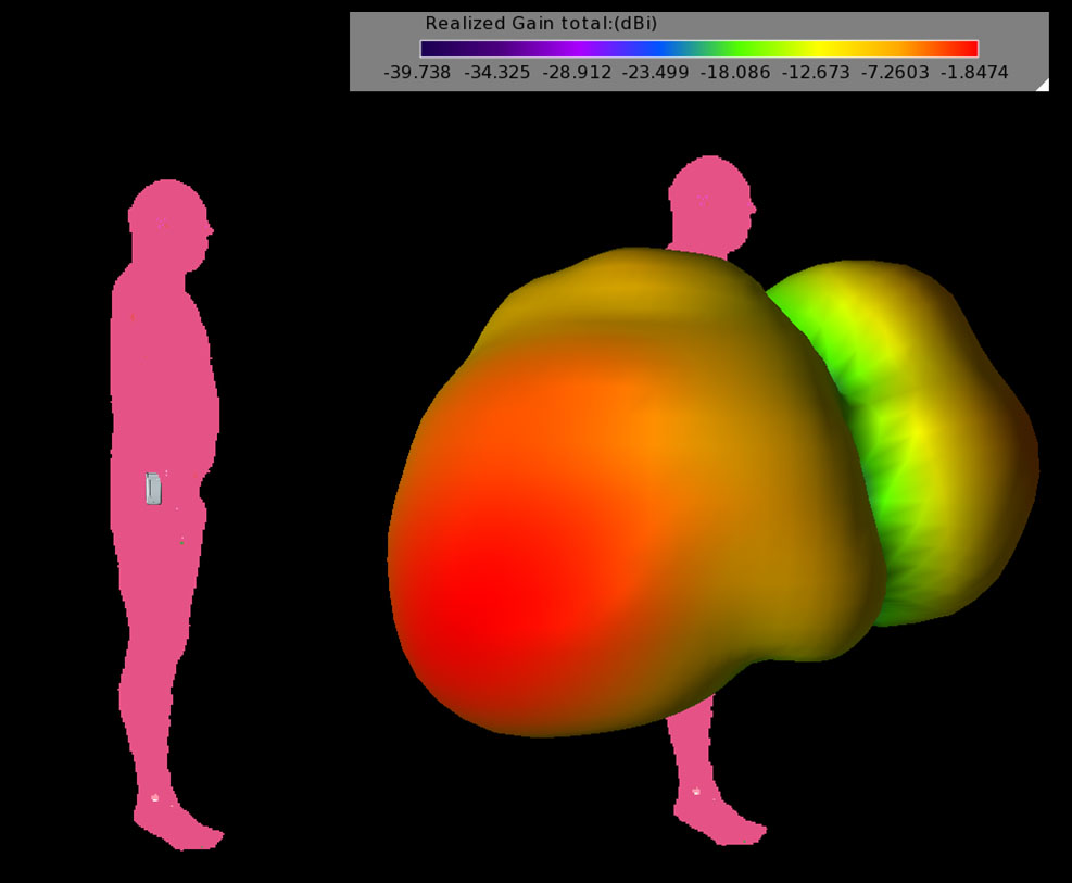
Figure 6: The gain pattern for walking man Position 2 where the arm is blocking the radiation from the phone and the pattern is split with the peak gain shifted to the rear.
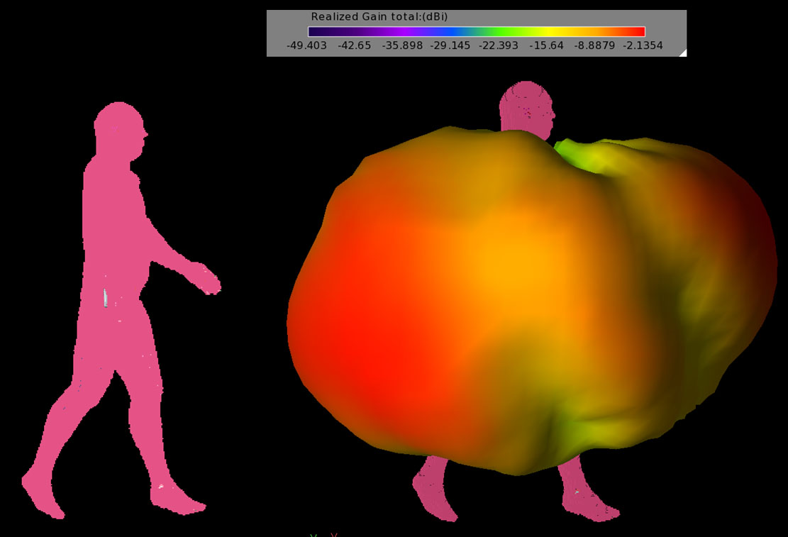
Figure 7: The gain pattern for walking man Position 3 where the right arm is still covering the phone. The pattern is similar to the neutral Position 2 case as the arm is in a similar position.
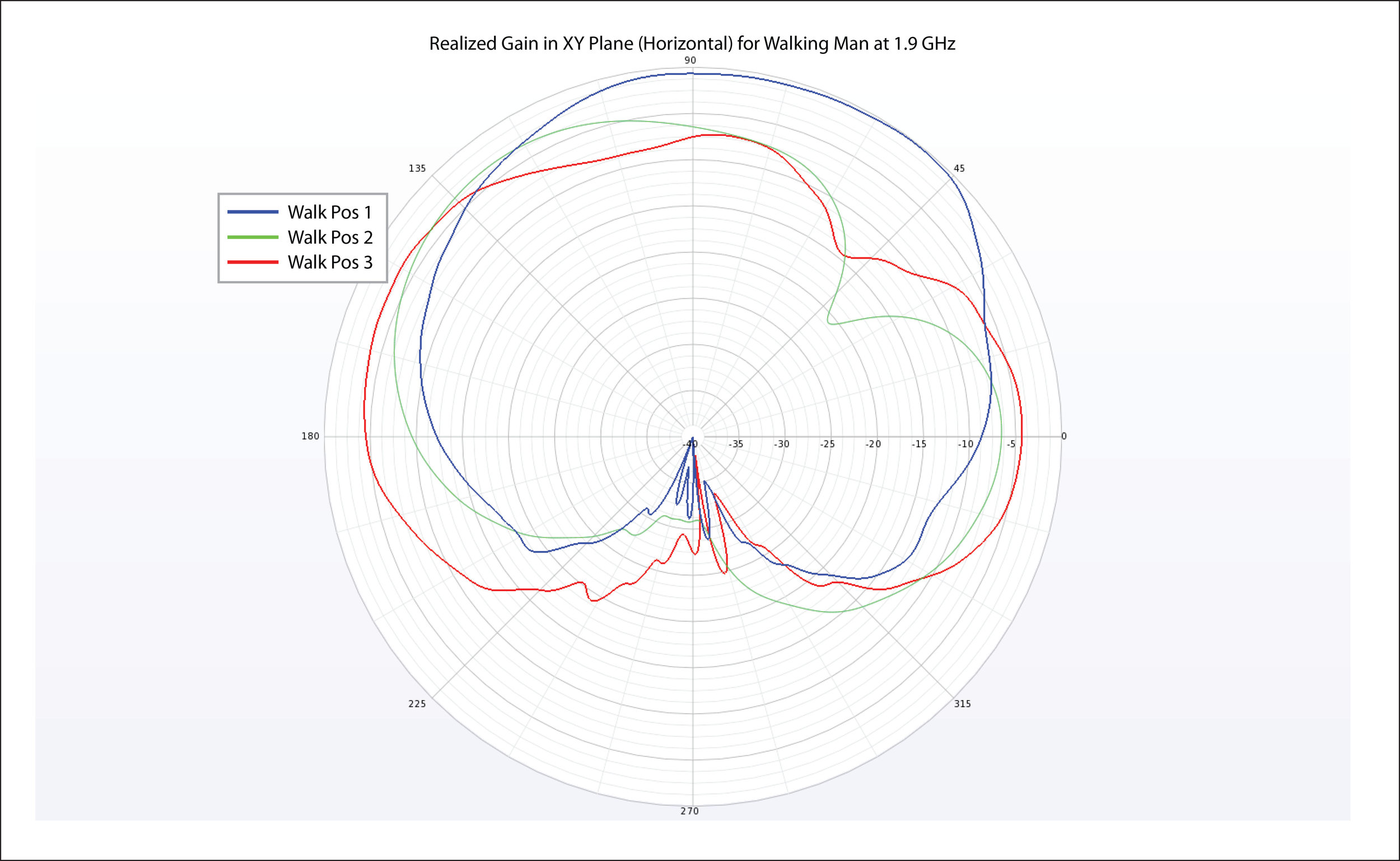
Figure 8: The planar gain pattern in the horizontal plane for the three positions of the walking man. In the plot the man is facing toward 0 degrees and the phone is at 90 degrees.
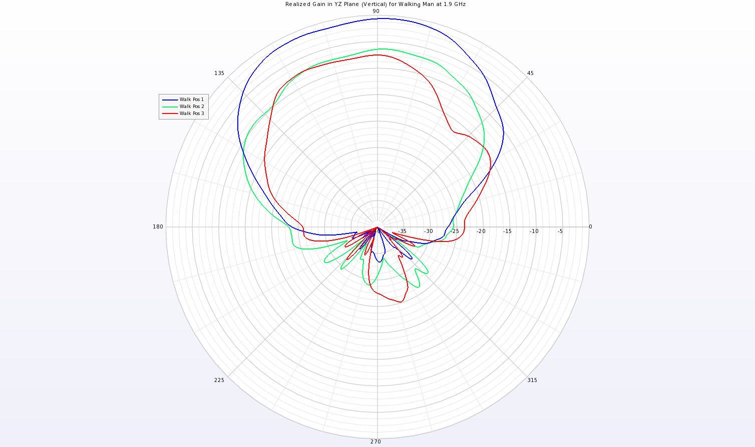
Figure 9: The planar gain pattern in a vertical slice that crosses the man from side-to-side with the phone positioned at the 90 degree point
It was clear from the first exercise that the arm position had a great impact on the cell phone antenna. For a second example, the position of the right arm is swept through a set of eleven positions in 10 degree increments to gauge the impact on the antenna performance. The movement of the arm in relation to the phone is shown in Figure 10, where all eleven positions are displayed.
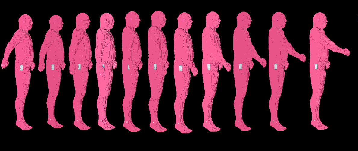
Figure 10: Shown are the eleven positions of the moving arm used in the simulations.
The movement of the arm has a large impact on the phone performance, in particular the gain pattern. In Figure 11, the gain pattern for the arm in the furthest back position (Position 1) is shown and the peak gain is to the side of the body. In Figure 12, the arm is in Position 4 and the gain pattern is significantly different with the peak gain to front of the body. By Position 10, shown in Figure 13, with the arm almost fully forward, the gain pattern can be seen to peak to the side of the body again. In Figure 14, the gain patterns of all eleven positions are show together where the white arrow indicates the direction of the peak gain. It is clear that the pattern shape and levels change significantly with the movement of the arm. The gain in the horizontal and vertical planes is shown in line plot format in Figures 15 and 16 for comparison.
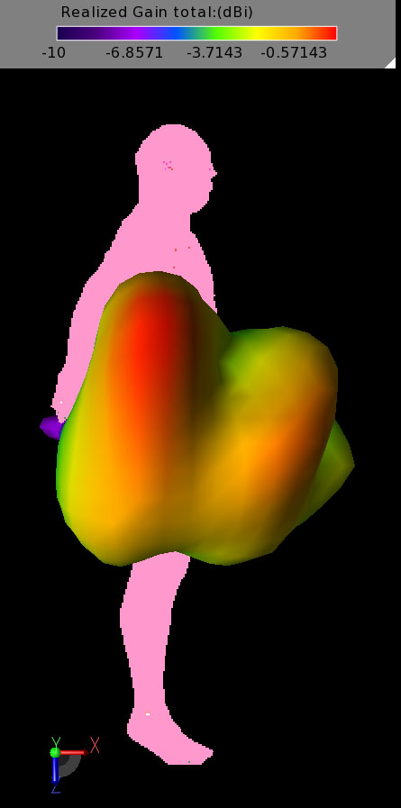
Figure 11: The gain pattern plotted for the arm in Position 1 which is to the rear. The arm is mainly out of the way of the radiation pattern and the peak gain is to the side of the body.
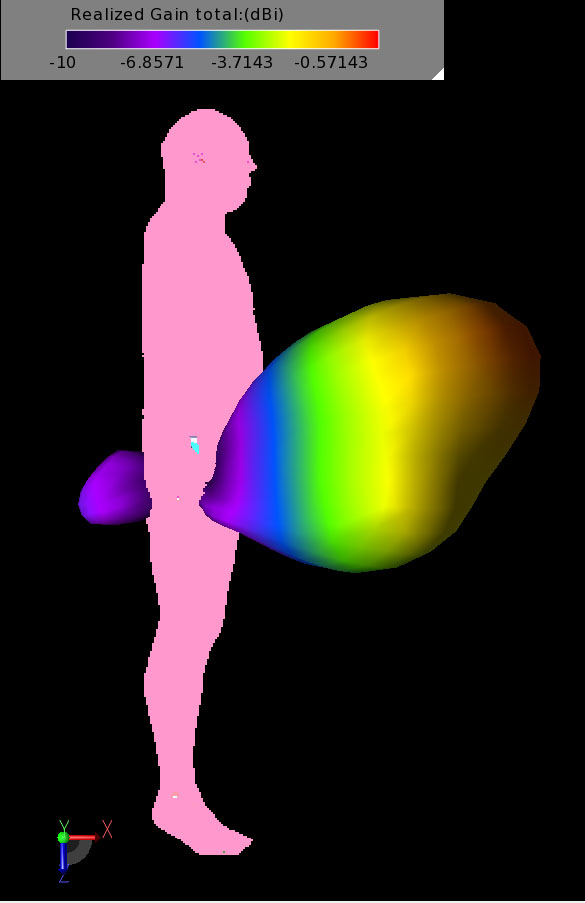
Figure 12: The gain pattern for the arm in Position 4 where the radiation from the phone is blocked. Here the peak gain is to the front of the man.
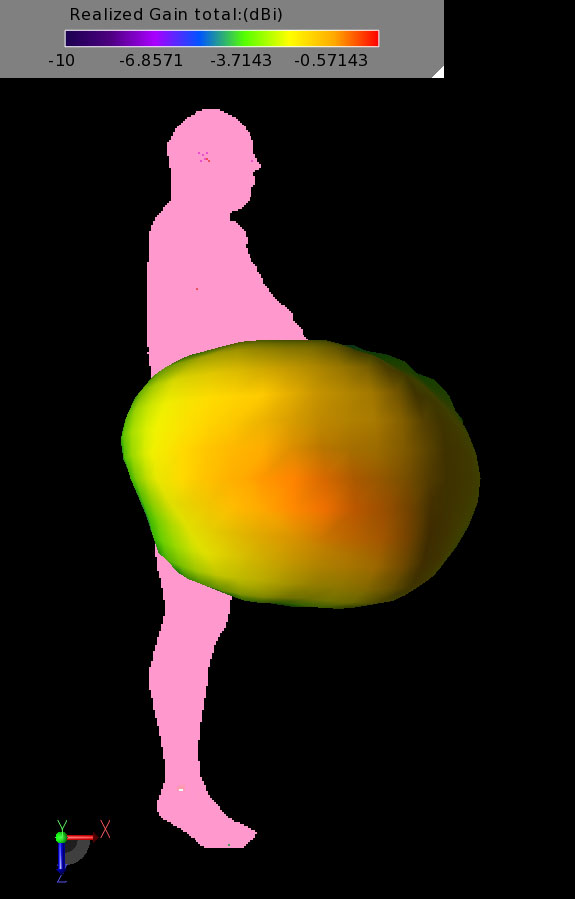
Figure 13: The gain pattern for Position 10 where the arm is mainly forward of the phone. The pattern is still impacted but the peak gain is again to the side of the body.
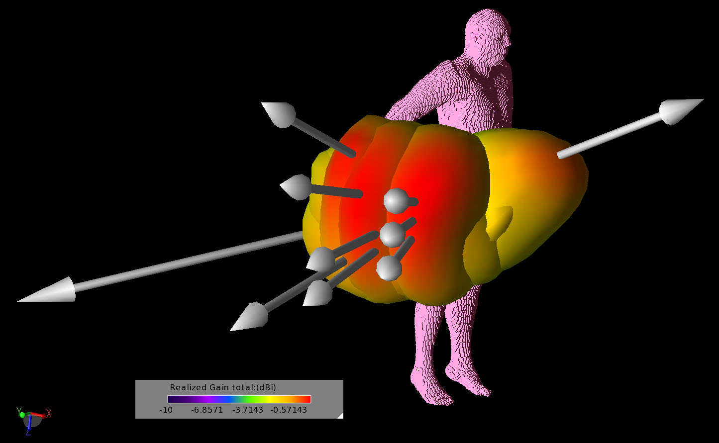
Figure 14: Shown are all eleven gain patterns for the different arm positions plotted together. The arrows indicate the direction of the peak gain which can be seen to shift significantly with arm position.
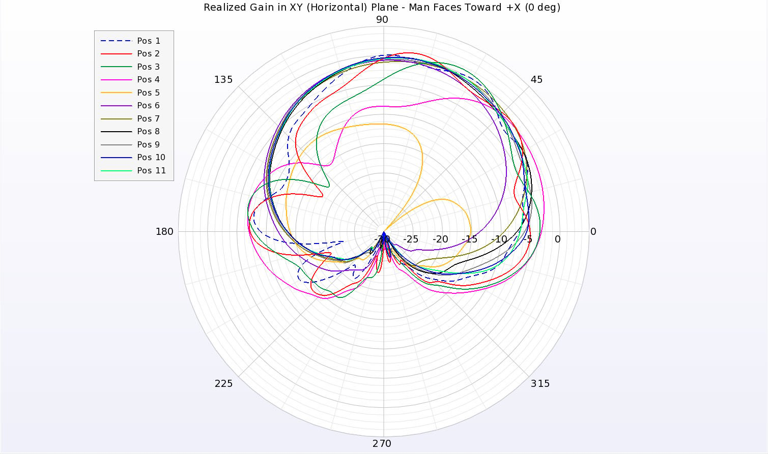
Figure 15: Shown is the planar line plot of the gain patterns for all eleven cases in the horizontal plane. Here the man faces to the 0 degree point and the phone is at the 90 degree point.
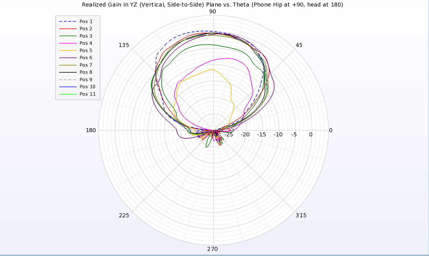
Figure 16: Shown is the planar line plot of the gain patterns for all eleven cases in a vertical plane that crosses the man side-to-side. The phone is located at the 90 degree point.
When comparing the feed point values of return loss and impedance, the movement of the arm has little impact. A summary of the values for all arm positions is shown in Table 2. The system efficiency also varies only slightly over all arm positions except in the case of Position 5 where the arm is directly over the phone and the efficiency drops significantly.
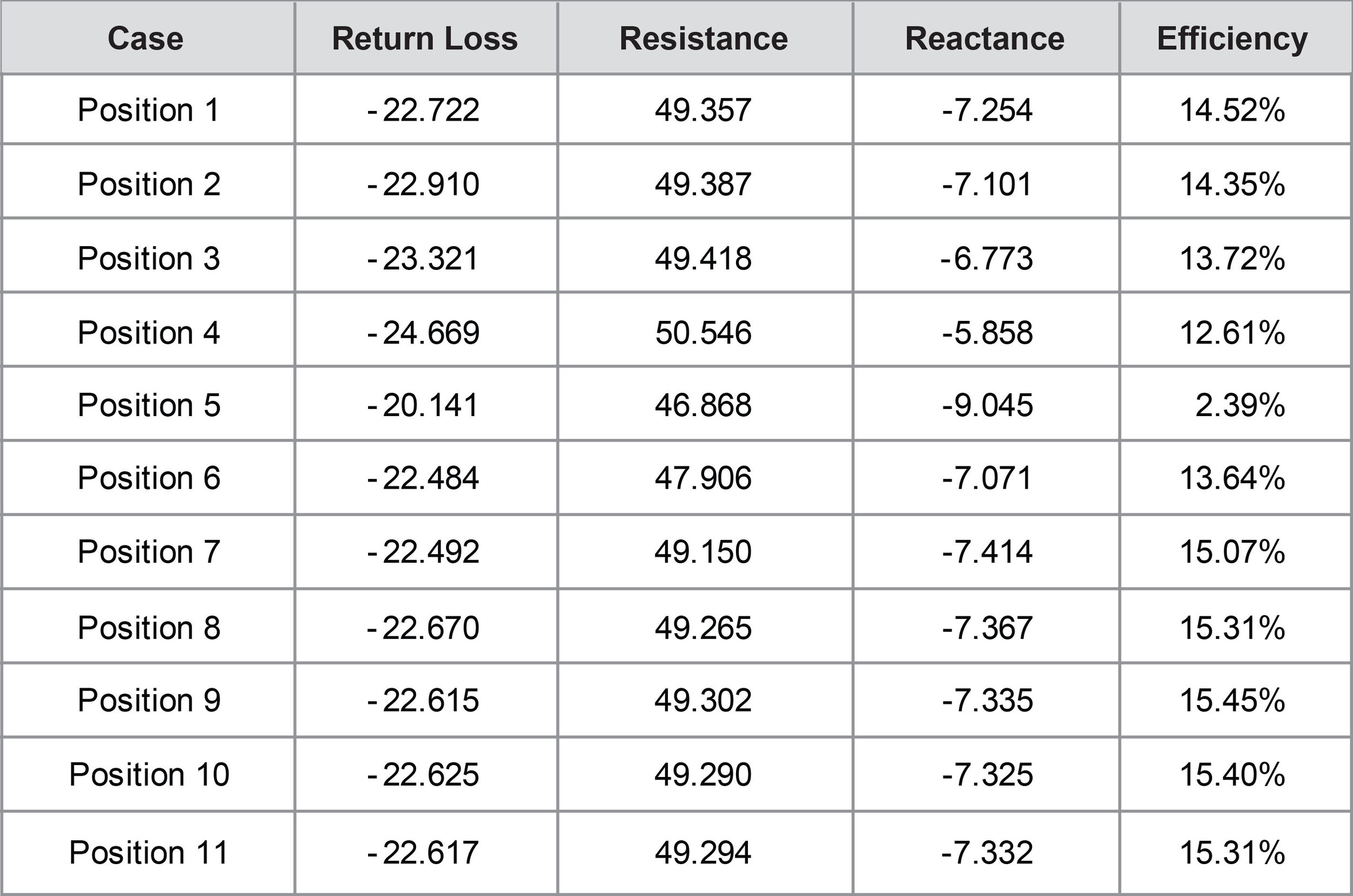
Table 2.
This set of examples has shown how the VariPose and XFdtd software products can be used together to analyze the performance of devices, in this case a cellular phone, in the dynamic environment of the moving human body.