This geometry comes from the paper "A New Circularly Polarized Rectenna for Wireless Power Transmission and Data Communication" by Mohammod Ali, G. Yang, and R. Dougal [1]. The geometry of the patch is detailed in Figure 1.
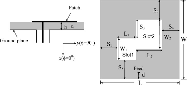
Figure 1: Published antenna schematic
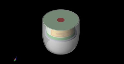
Most of the important parameters are presented in the text; however, two critical pieces of information are omitted. Neither the radius of the coax conductor nor the horizontal positioning of the feed are mentioned. The sketching and constraint tools are used to create the patch geometry using the same parameters outlined in the paper as seen in Figure 2. New parameters are added to control the feed radius and horizontal positioning.

Figure 2: Antenna in XFdtd
A non-uniform base cell size of 0.5 x 0.5 x 0.3175 mm is defined, and a 0.1 x 0.1 mm XY automatic grid region is defined for the surface of the patch. Automatic fixed points are employed on the center conductor of the coaxial cable in order to localize the use of small cells. A CPML outer boundary condition is used with a 30 cell padding around the entire structure.
A brief parametric analysis is performed to explore the effect of the feed radius and horizontal positioning on return loss. The horizontal positioning is defined as an offset from the center of the patch in this case. Figures 3, 4, and 5 demonstrate the impact of these variables. Through this analysis, a feed radius of 0.05 mm and a feed position of 0.16 mm is chosen for the remaining analysis. XFdtd's built-in scripting language is used to load the measured return loss from the paper and plot them side-by-side with the simulated results in Figure 6.
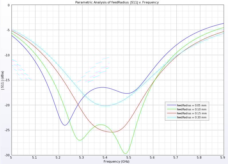
Figure 3: Return loss versus feed radius
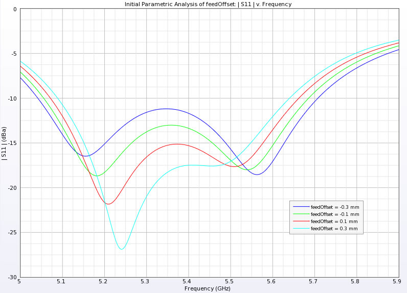
Figure 4: Initial investigation of return loss versus feed position
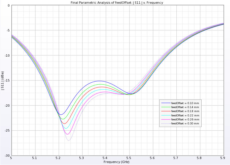
Figure 5: Final investigation of return loss versus feed position
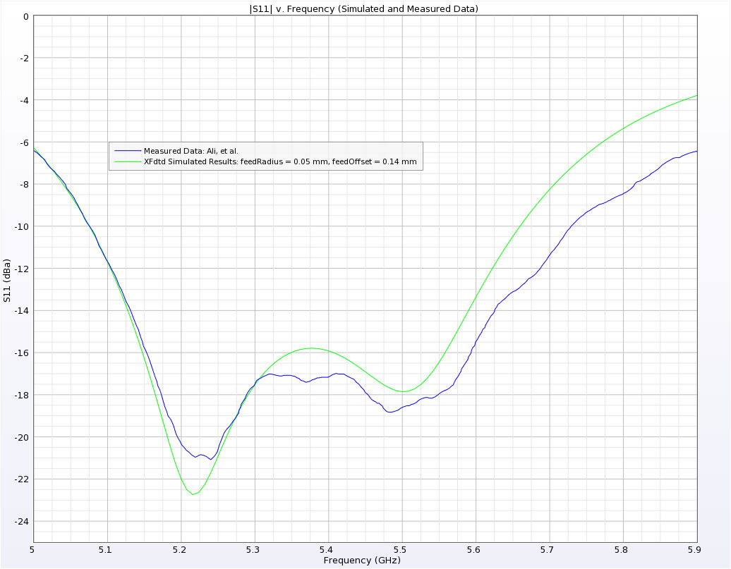
Figure 6: Comparison of simulated and measured
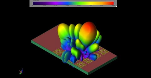
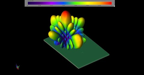
A steady-state CW simulation at 5.5 GHz was performed in order to obtain 3D radiation patterns. Figures 7 and 8 display 2D polar plots of the phi and theta results respectively. Figures 9 - 13 demonstrate the total, theta, phi, LHCP, and RHCP gains in 3D respectively.
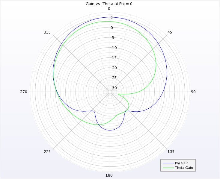
Figure 7: Phi and theta gains at phi = 0 degrees
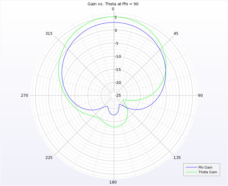
Figure 8: Phi and theta gains at phi = 90 degrees
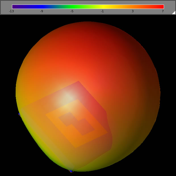
Figure 9: Total gain
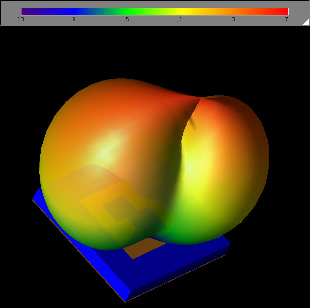
Figure 10: Theta gain
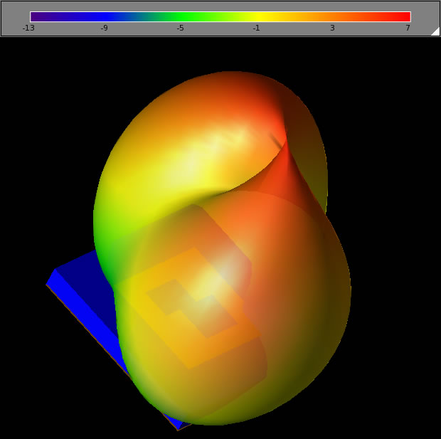
Figure 11: Phi gain
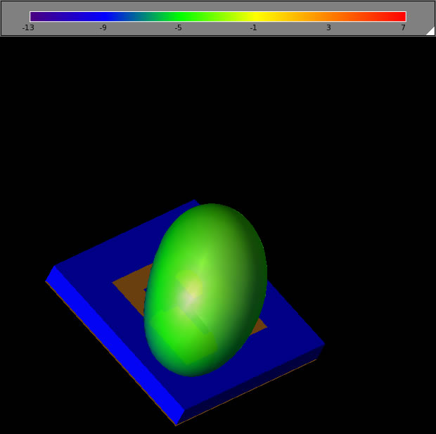
Figure 12: LHCP gain
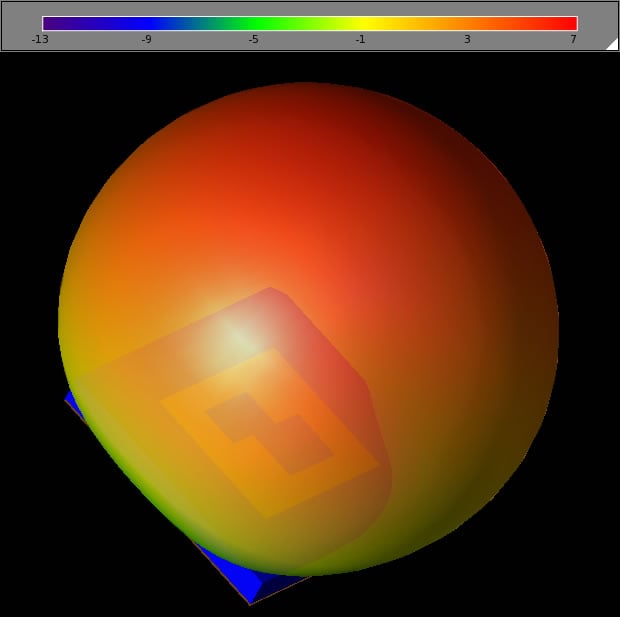
Figure 13: RHCP gain
Reference
-
M. Ali, G. Yang, and R. Dougal. "A New Circularly Polarized Rectenna for Wireless Power Transmission and Data Communication." IEEE Antennas and Wireless Propagation Letters, vol. 4, pp. 205-208, 2005.