This example duplicates results provided in the paper "An Inverted FL Antenna for Dual-Frequency Operation" by Nakano, Sato, Mimaki, and Yamauchi [1]. The Inverted FL antenna is a planar antenna designed to operate at 2.45 and 5.2 GHz. This antenna is extremely easy to analyze using XF. The geometry of the planar antenna is shown in Figure 1.
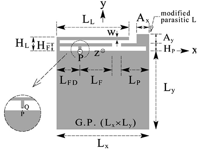
Figure 1: The Dual Frequency Inverted FL Antenna geometry
The paper includes complete dimensions for the antenna. It is easily drawn using the sketching tools in XFdtd. The snapping tools and construction grid settings make the creation of the antenna very quick. The antenna is sized using the constraint tools. The sketch in progress and the finished antenna are shown in Figures 2 and 3.
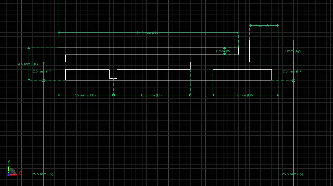
Figure 2: Dual Frequency Inverted FL Antenna in 2D Sketcher
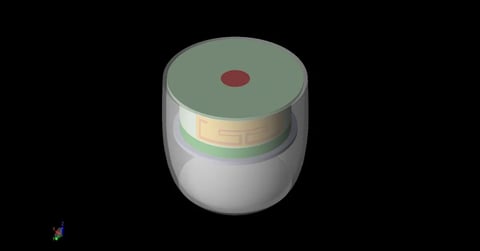
Figure 3: Finished antenna
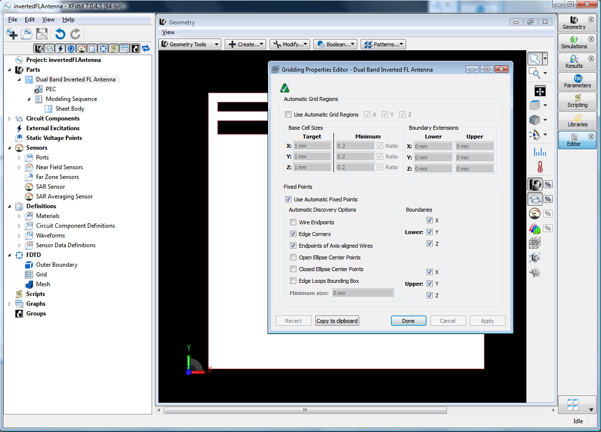
Figure 4: Automatic fixed points from the antenna geometry
The antenna geometry used automatic fixed points to ensure the most accurate representation in the mesh. The grid automatically creates smaller cells near the smaller features of the antenna producing a higher-fidelity representation where needed.
The calculation is performed with a transient excitation to determine the resonant frequencies of the antenna. The resulting VSWR vs Frequency plot is shown below in Figure 6. Figure 7 shows the experimental results from the paper. Clearly XFdtd produces a very accurate result.
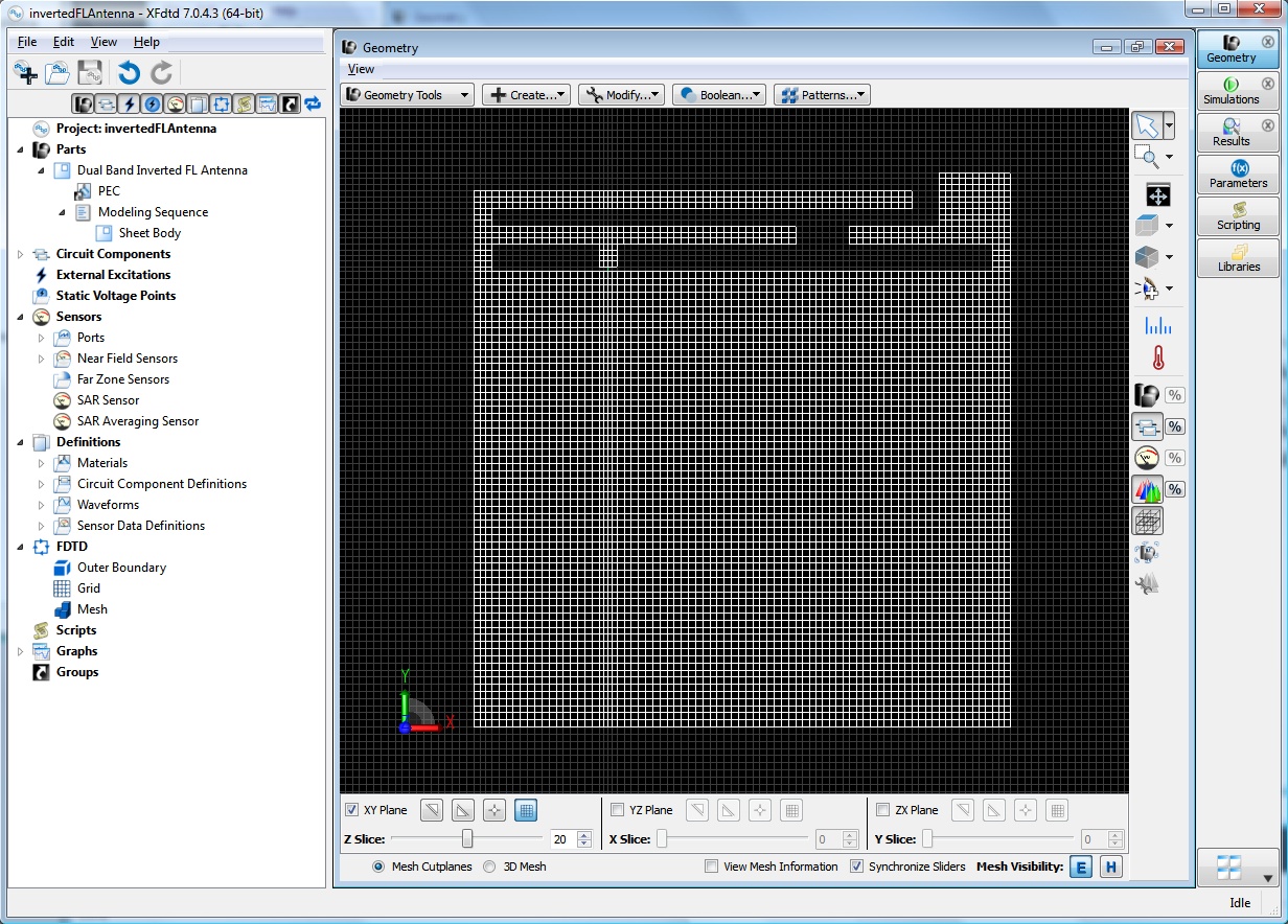
Figure 5: Meshed antenna with variable cell sizes
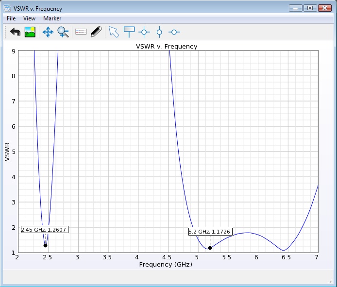
Figure 6: Simulated VSWR results
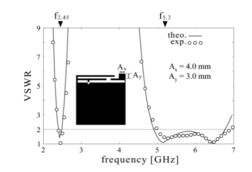
Figure 7: Theoretical and experimental results
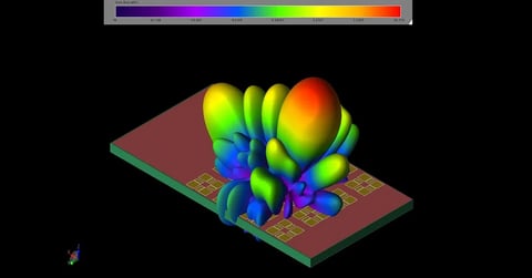
Figure 8 shows the antenna current distribution at 2.45 GHz. Note that the current on the long 'L' part of the antenna at the upper left of the antenna is relatively strong at this lower frequency.
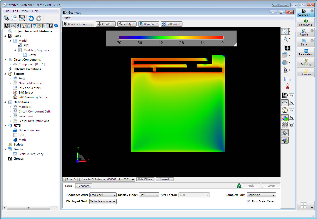
Figure 8: Steady-state current magnitudes at 2.45 GHz
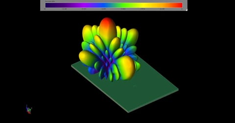
Figure 9 shows the corresponding current density at 5.2 GHz. At this higher resonance the current is stronger on the shorter 'F' portion of the antenna and on the modified parasitic 'L' at the upper right. The dual frequency nature of this antenna is clear from considering these two current displays.
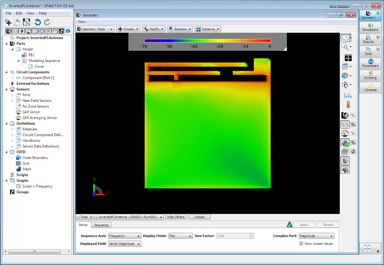
Figure 9: Steady-state current magnitudes at 5.2 GHz
Reference
-
Nakano, Sato, Mimaki. "An Inverted FL Antenna for Dual-Frequency Operation.” IEEE Transactions on Antennas and Propagation, vol. 53, no. 8, pp. 2417-2421, August 2000.