EM Simulation of Automotive Radar Mounted in Vehicle Bumper
 Summary:
Trends in automotive safety are pushing radar systems to higher levels of accuracy and reliable target identification for blind spot detection and collision prevention assistance. Consequentially, engineers need to better understand how mounting brackets, fascia, paint color, and bumper assemblies affect the far field radiation patterns of 24 GHz and 77 GHz automotive radar systems. Long used for lower frequency (and longer wavelength) antenna-on-vehicle simulations, including vehicle-to-vehicle communication, electromagnetic (EM) simulation can now handle high fidelity analysis beyond the ideal 24 GHz and 77 GHz sensor itself, to include the antenna package and the automobile body features surrounding the device.
In this paper, a 24 GHz sensor is used to discuss differences between the simulation of a stand-alone sensor and one that is mounted in a vehicle. Efficient finite-difference time-domain (FDTD) EM analysis, combined with dramatic computation acceleration via CUDA-enabled graphics processing units (GPUs), make Remcom’s XFdtd®, a fully arbitrary 3D EM simulation software tool, an optimal choice for the simulation of an antenna-in-system design with this level of complexity.
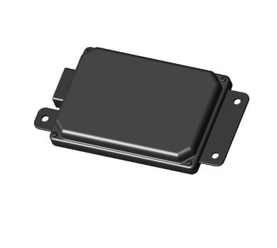
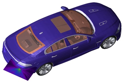
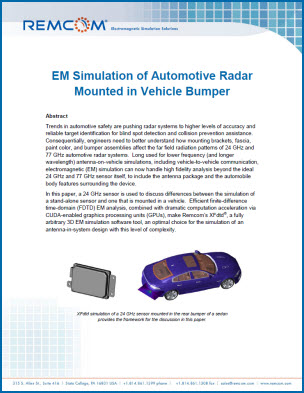
XFdtd simulation of a 24 GHz sensor mounted in the rear bumper of a sedan provides the framework for the discussion in this paper.
Design Challenges at High Frequencies
The shorter wavelengths of 24 GHz and 77 GHz pose design challenges that are not present in applications at lower frequencies, like vehicle-to-vehicle communication at 5.9 GHz. At the sensor level, structures in the PCB layers become electrically large and can cause unexpected interference. Likewise, when the sensor is mounted in a vehicle, the thickness of the fascia can distort radiated waves and cause undesired reflections. Some of these issues lead to changes in the sensor’s design, while others are better addressed by providing guidelines to automobile manufactures. Regardless, engineers need a tool that permits a high fidelity analysis to be performed and allows them to ferret out issues in their design while considering all aspects affecting a sensor’s performance.
Radar is Inherently Time Domain
Radar is an inherently time domain process: a signal travels out from a transmitter, reflects off of an object, and returns to the receiver. While much of radar design occurs at a systems level with mathematical signal processing concepts, signal integrity problems can occur on the local radar circuit board and adversely affect overall radar system performance. Simply looking at the frequency content of these unwanted current or voltage problem areas may not provide enough information to thoroughly design or troubleshoot the radar system.
FDTD EM simulation has the ability to show the motion of signals as a function of time. Tracking the source of a particular current or voltage coming into a problem area in the circuit can reveal the root source of a performance problem in a radar device. The problem might come from unwanted coupling among signal traces on the board. The problem might result from energy ringing down from the antenna or other high Q portion of the circuit. These time-dependent phenomena cannot be seen clearly with a purely frequency domain approach; time domain simulation is needed to find these types of problems.
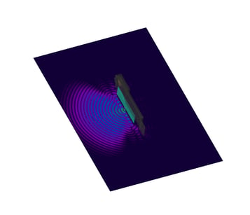
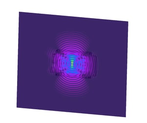
Time-domain fields show interactions within the sensor.
Further, once the sensor is mounted to a vehicle, interference at the received antenna can make target identification difficult. This interference may be caused by a resonance setup in the bumper assembly or reflections from the mounting brackets. FDTD EM simulation and GPU computer technology now allow the inclusion of larger structures, such as the bumper or back end of an automobile, to be included in automotive radar device simulations. High fidelity EM simulations of 24 GHz or 77 GHz radar mounted inside automobile bumpers can help application engineers and their customers thoroughly troubleshoot antenna performance and how it changes with vehicle structure and materials during the design cycle.
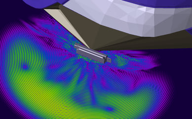
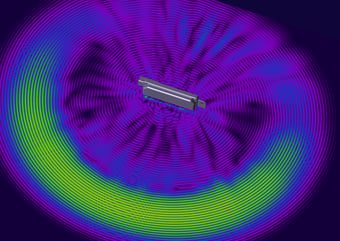
Distribution of electric fields 1.8 ns after being launched.
The figures above compare electric fields as they radiate away from the sensor. Unlike the stand-alone case on the right, the case on the left shows the fascia trapping waves. This is undesirable because it distorts the transmitted fields and because the trapped fields reflect back into the receiver, causing interference.
Parameterization Explores Beyond the Antenna
Automotive radar design needs to analyze and simulate more than the ideal frequency domain antenna characteristics alone. Packaging details close to the antenna as well as vehicle body features a meter or so away from the antenna also affect the antenna far field patterns and the radar system performance. Starting right in the antenna construction, the alignment of multiple layers (registration) during assembly can affect the performance of the antenna. The edge effects of a circuit board dielectric, mounting screws holding the circuit board to a package, and any package cover or radome over the antenna can alter the antenna radiation pattern or cause time domain reflections back to the antenna that don’t appear in systems level design. Moving beyond the automotive radar device packaging, the bumper and entire nearby section of the vehicle will also affect the antenna and radar system performance. Taking into account vehicle and bumper materials, shapes, dimensions, and device packaging creates many variables to explore in radar system design.
One approach to testing multiple dimensions of variation – bumper materials, paint coatings, and thicknesses – is via parameter sweeps in EM simulation. Most any quantity specified in a simulation can be done so using a variable and therefore swept over a range of values in an automated way. Parametric sweeps can vary geometries such as the mounting location of the automotive radar device horizontally along the bumper and around its curving corner. Nested sweeps varying more than one parameter at a time are useful for exploring the design space early in the design cycle and gaining valuable understanding and intuition about the system performance. Sensitivity analyses and optimizations also change parameter values in multiple simulation iterations; typically these are used later in the design cycle for validation.
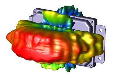
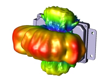
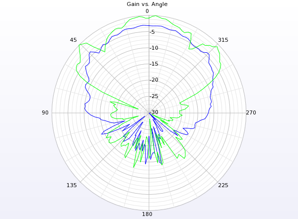
Parametric analysis is used to improve design performance.
Vehicle Simulation Size Relative to Wavelength
The simulation of individual antenna structures and their far field radiation patterns has been a staple of EM simulation software for many years. This includes free-standing antennas as well as on-chip antennas closely connected to amplifiers in integrated circuits (ICs). More recently, with the advent of 64-bit computing and the increase in RAM that it makes available for individual simulations, EM simulation has expanded to include antennas and vehicles together; however, the vehicle might be represented in a different EM formulation that may only look at the surface metal of a car, satellite, ship, or airplane.
The challenge to achieving high-accuracy simulation of antenna structures and vehicles together, using one fully arbitrary 3D EM simulation, has been the simulation problem size, often described in terms of the number of elements in the mesh or how much RAM (memory) the problem consumes. A simulation requiring too many GB of RAM becomes impractical either because it takes too many hours to run or because the simulation goes completely beyond the available computer hardware capability.
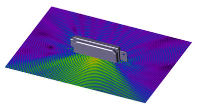
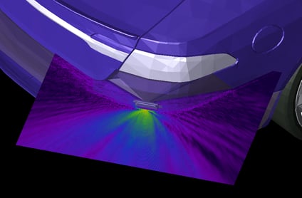
GPUs reduce simulation time for 4 GB and 20 GB problems.
EM simulation of an antenna generally scales with signal frequency because the EM simulation accuracy is based largely on the number of mesh cells per wavelength. A half-wavelength dipole antenna simulation takes about the same amount of simulation time at low or high frequency because the mesh cell size scales to the antenna dimension based on wavelength. Simulation of an antenna mounted on a vehicle in one fully arbitrary 3D EM simulation includes both structures. Higher signal frequency means smaller wavelength and a smaller cell size is needed in order to accommodate the antenna. This smaller mesh means more mesh cells are utilized to simulate the portions of the car.
Mesh size can vary within one simulation, with larger mesh cells of 1.25 mm around large physical features like bumper assemblies and smaller mesh cells of 0.04 mm near finer geometries like the feeding structure of a sensor’s antenna, but there is always a limit to the range in mesh size that is practical or accurate for a single simulation. The ability to now simulate a high frequency radar device and antenna along with the bumper area of a car in one fully arbitrary 3D EM simulation is a benefit of the FDTD method of EM simulation. FDTD provides both the ability to scale mesh size linearly with problem size and to leverage tremendous efficiencies with CUDA-enabled GPU systems.
FDTD Simulation Scales Linearly with Problem Size
In the world of fully arbitrary 3D EM simulation, there are frequency domain and time domain formulations. Although both types can simulate steady state frequency domain data, including S-parameters, there are differences in how quickly the simulation time grows as the simulation problem size grows. There are frequency domain EM simulation formulations where the simulation time grows at a rate of n-squared, where n is the problem size. One of the advantages of FDTD simulation for large problem sizes is that time domain simulation execution time grows only linearly as the simulation problem size grows1. The larger the problem size, the greater the relative benefit of time domain simulation versus frequency domain simulation.
Time domain simulators run an entire simulation for each port in a design. Generally frequency domain simulators don’t need to do this. For some simulations with many ports, a frequency domain EM formulation, such as finite element method (FEM), may be a good choice. For an antenna application that does not involve many signal ports in a design, time domain simulation has the advantage for large problem sizes.
FDTD Parallelizes Well with GPUs
A popular approach to simulating large EM structures quickly utilizes CUDA-enabled GPUs. CUDA, the Compute Unified Device Architecture, is a parallel computing platform created by NVIDIA and implemented by the graphics processing units (GPUs) that they produce. Originally developed for accelerating video graphics, GPUs are popular for many high performance computing (HPC) applications.
The comparison between GPU and traditional CPU computing is dramatic. GPUs can apply hundreds of processors where CPUs can only offer a few. More than frequency domain EM simulation, time domain EM simulation parallelizes well; FDTD can take full advantage of the simulation time acceleration offered by GPUs.
Summary
Designing an automotive radar sensor is a challenging task even before introducing the complexities of mounting brackets and bumper assemblies. Computational FDTD EM simulation offers the tools necessary for engineers to perform a high fidelity analysis of the sensor while considering final mounting configurations. This is enabled by XFdtd’s XStream® GPU Acceleration technology that tremendously reduces EM simulation time by leveraging GPUs and enabling XF to make ultra-fast FDTD numerical computations. In the end, engineers can move the automotive safety industry forward by increasing the reliability and accuracy of radar systems.
References:
[1] Microwave Circuit Modeling Using Electromagnetic Field Simulation by Daniel G. Swanson, Jr. and Wolfgang J. R. Hoefer, Artech House c 2003 ISBN: 1-58053-308-6
