The geometry is taken from the paper “A New Design of Horizontally Polarized and Dual-Polarized Uniplanar Conical Beam Antennas for HIPERLAN” by Neil J. McEwan, Raed A. Abd-Alhameed, Embarak M. Ibrahim, Peter S. Excell, and John G. Gardiner [1]. The geometry of the patch array is shown in Figure 1. The patch array is mounted on a 75 cm square metal finite ground plane covered with a 1.524 mm dielectric substrate with relative permittivity 2.55 and loss tangent 0.0024. The patches are designed to resonate at 5.0 GHz.
The paper includes all of the information necessary to create a patch antenna that properly resonates at 5 GHz; however, certain parameters affecting performance are omitted. The "Vertical Offset" denoted in Figure 1 represents one such characteristic. The sketching and constraint tools are used to create a fully parameterized model that permits us to investigate the effect of varying the vertical offset. The sketch of the feed line in progress is shown in Figure 2, and one completed patch is displayed in Figure 3. Once one element of the array is completed, the Circular/Elliptical Pattern tool is used to automatically create the remaining array elements (Figure 4). The resulting completed XFdtd geometry is presented in Figure 5.
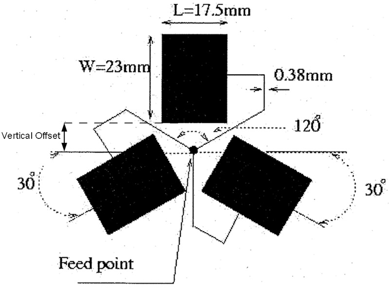
Figure 1: Geometry from paper
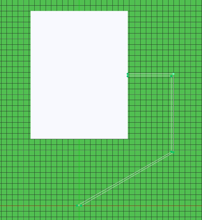
Figure 2: Sketch of feed line
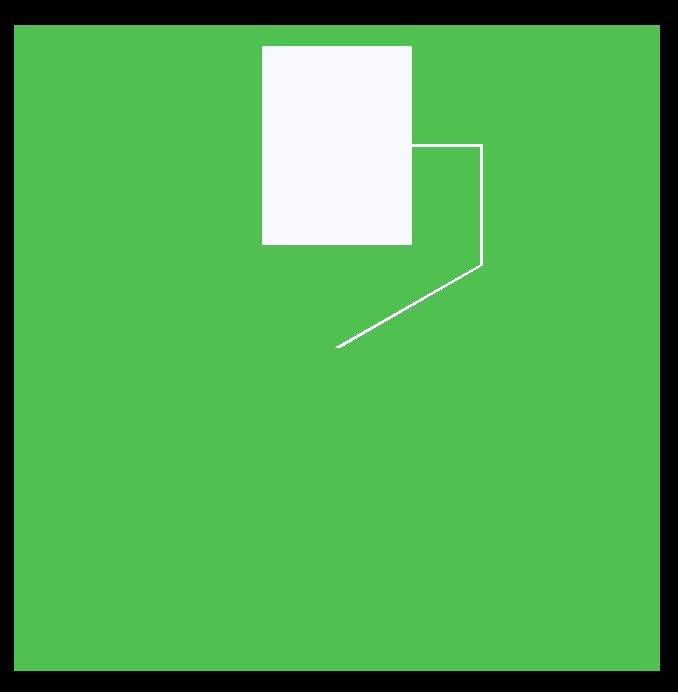
Figure 3: One completed patch with feed line
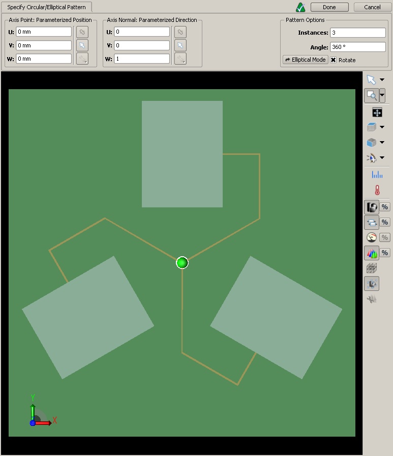
Figure 4: Defining the other two patches

Figure 5: Complete geometry
A relatively large base cell size of 1 mm is used to save memory while a combination of grid regions and automatic fixed points are used to place smaller cells precisely where they are needed. These features combine to yield an excellent discretized representation of the antenna geometry that requires a minimal memory footprint and a simulation that completes quickly.
Before investigating the far-zone performance of this array, a parameter sweep is performed to determine a value for the vertical offset which will result in a good antenna performance at 5 GHz. Watch the brief movie showing how the geometry in XF automatically updates based on the changing value of the vertical offset parameter. Values ranging from 6 mm to 12 mm were investigated, and Figure 6 shows that larger values result in much better performance at the frequency of interest. As a result, the vertical offset was set to 12 mm for the far-zone evaluation.
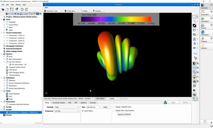
Figures 7 and 8 show the resultant steady-state E field and surface current distributions respectively. Figure 9 is a 3D visualization of the far-zone pattern while Figure 10 presents several 2D far-zone cuts which show good agreement with measured results presented in the paper.
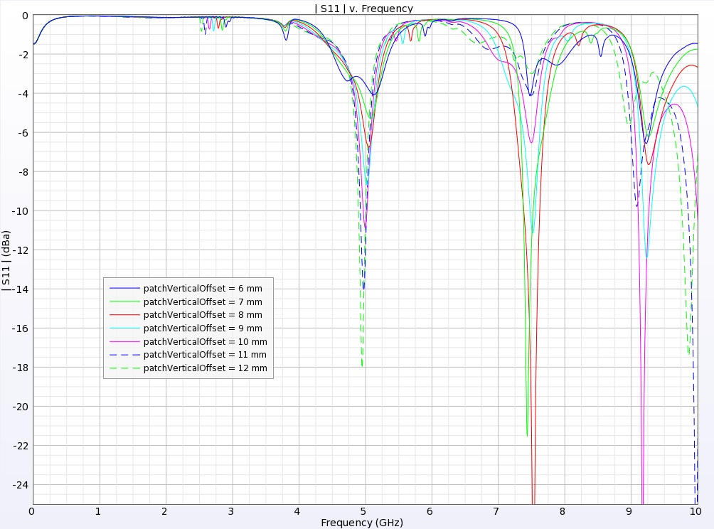
Figure 7: Return loss for each parameter value
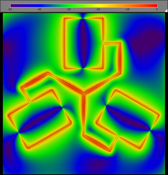
Figure 8: Steady-state electric fields on the antenna surface
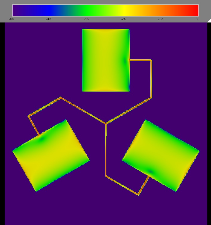
Figure 9: Surface current distribution on the patches
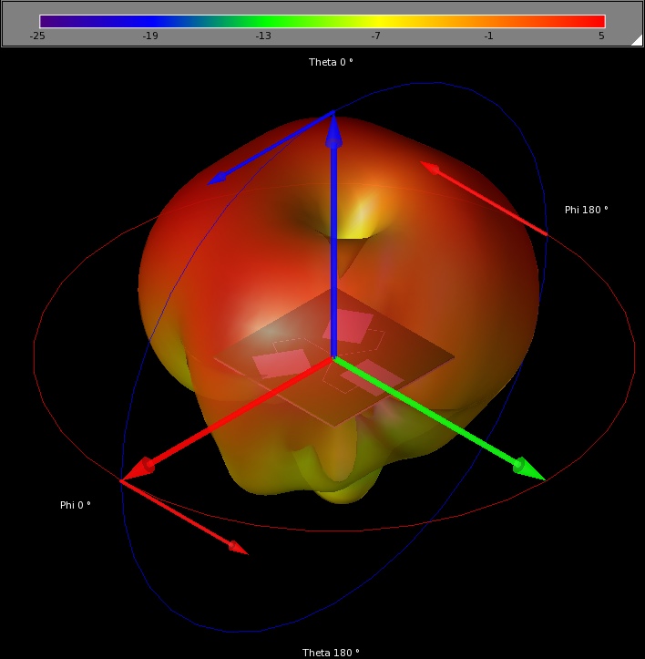
Figure 10: 3D far-zone radiation pattern
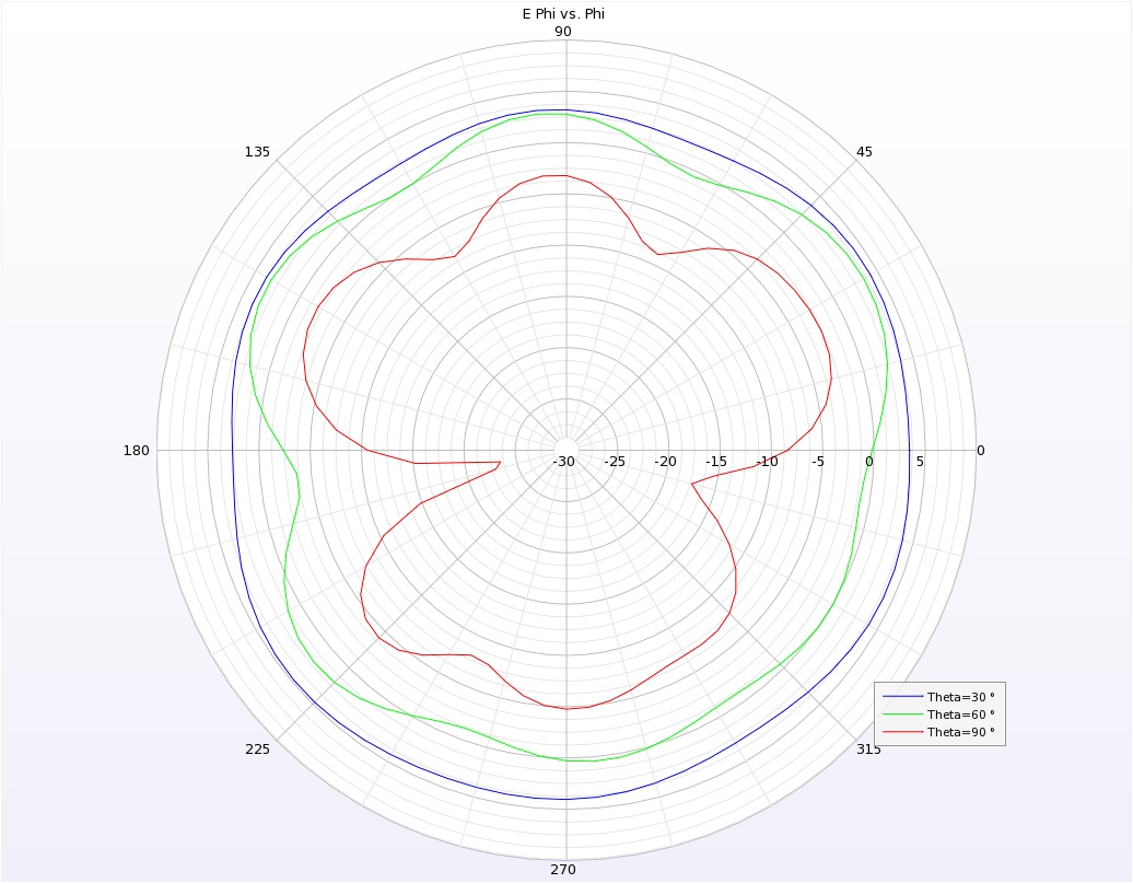
Figure 11: 2D slices of far-zone fields
Reference
-
Neil J. McEwan, Raed A. Abd-Alhameed, Embarak M. Ibrahim, Peter S. Excell, and John G. Gardiner. “A New Design of Horizontally Polarized and Dual-Polarized Uniplanar Conical Beam Antennas for HIPERLAN.” IEEE Transactions on Antennas and Propagation, vol. 51, no. 2, February 2003.