This microwave circulator is a microstrip design with a 12 mm radius. The magnetized ferrite material has a biasing field of 300 Oe in the -z direction perpendicular to the circulator plane and a saturation magnetization of 300 Gauss. The three microstrip lines forming the ports are terminated with 120 ohm resistors which approximately match the characteristic impedance of the microstrip. Figure 1 shows the circulator mounted on a metal ground plane.
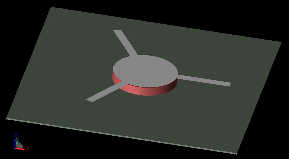
Figure 1: Ferrite circulator structure.
The circulator is excited at Port 1 with a broadband input. S-Parameters were collected from a simulation and can be observed in Figure 2. The plots of S11, S21, and S31 show the first resonance near 6.6 GHz. At this frequency, Port 2 is 10 dB smaller than Port 3 while Port 1 is matched.
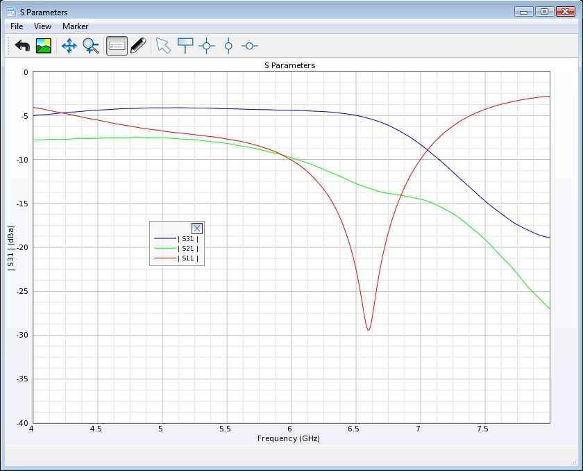
Figure 2: Broadband S-Parameters showing the isolation at the receive ports.
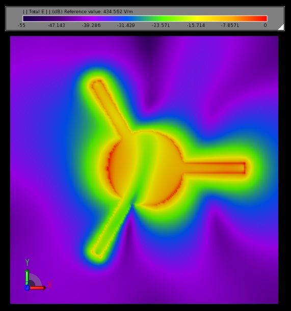
Steady state electric fields were also collected at 6.6 GHz, as shown in Figure 3. The null at Port 2 can be seen and is due to the interfering waves traveling around the ferrite at different velocities.
Figure 3: Steady state electric field strength at 6.6 GHz.
Request Project Files
Thank you for your interest in this application example. Please complete the form below to download the Ferrite Circulator Analysis Using XFdtd project files.
Learn how our products can simplify your EM analysis projects today.
In this example, a compact Ku-band antenna array is demonstrated for use in mobile device applications. The antenna is tuned for 12.5 GHz operation and contains a 4x4 array of elements which each consist of a set of patch antennas oriented and phased to produce a circularly-polarized far field pattern. The antenna array has peak gain over 20.7 dBi with sidelobes less than 8 dBi and a 3 dB beamwidth of about 15 degrees.
A 140 GHz slot antenna array excited by a substrate integrated cavity is demonstrated for use in wireless communications. The antenna array has high gain, wide bandwidth, low fabrication costs, and small size, which make it an effective design. The final 8x8 antenna array has bandwidth from 130 to 145 GHz, peak gain of 20.5 dBi, and radiation efficiency around 60%.
This example demonstrates the performance of a remote camera with two-element antenna arrays for 2.4, 5, and 6 GHz capabilities for 802.11 a/b/g/n/ac/ax. The maximum coverage possible at each frequency is discussed to demonstrate the capabilities of the device as part of a connected home system communicating with a MU-MIMO router.