Diplex Matched Antenna Tutorial Using XFdtd’s Schematic Editor
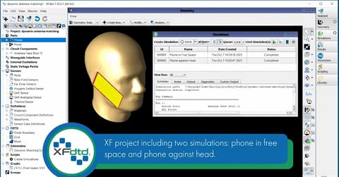
XFdtd’s schematic editor provides the capability to connect two voltage sources to a single antenna, improving workflow efficiency for diplex matched antenna use cases. System and radiation efficiencies can be effortlessly computed from a single schematic for two operating modes. This tutorial demonstrates XF's workflow for evaluating a diplex matched antenna and analyzing two different matching network states simultaneously.
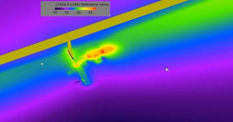
The antenna in this workflow example is a dual-band antenna designed for the GPS L1 band and the 2.4 GHz WiFi band containing channels 1 - 14. First, the characteristic impedance of the antenna is determined via an FDTD simulation and then a matching network is evaluated to see the matched performance of delivered power.
Visit our support site to explore the full tutorial and learn more about the following:
-
Review the workflow for setting up the FDTD simulation, including geometry specification, component placement, and simulation creation.
-
Examine the antenna's unmatched full-wave results.
-
Use XF's schematic editor to create and simulate a diplex matching network and evaluate the antenna's two operating modes–one for the GPS band and one for the WiFi band.
-
Analyze results including s-parameters and system efficiency.
Learn more about our antenna simulation software…
Learn more about matching network design and simulation in XFdtd…
2.webp?width=480&height=251&name=maxresdefault%20(2)2.webp)