 Summary:
To meet the increasing accuracy needs of high performance automotive radar design work, the FDTD EM simulation method has emerged as a better solution than traditional FEM formulations. FDTD overcomes FEM limitations that force design engineers to trade away accuracy and to simplify their simulation models. This paper introduces FDTD’s advantages for automotive radar circuit and systems level designers.
Electromagnetic simulation has been used by RF engineers for many years to aid the design of automotive radar sensors, but the increasing demands of advanced driver assistance systems (ADAS) are changing the methods used. Accurate modeling of increasingly complex circuits and antenna systems leads to simulation problem sizes too large (in terms of physical memory – RAM) for traditional frequency-domain finite element method (FEM) formulations. As a result of those limitations, design engineers who use FEM tools are forced to simplify their simulation models to fit the computational resources available, trading away accuracy and limiting the effectiveness of their simulator.
To meet the increasing accuracy needs of high performance automotive radar design work, the finite-difference time-domain (FDTD) method has emerged as the solution. Not only can FDTD give engineers accuracy by simulating large problems using graphical processor unit (GPU) technology, FDTD allows users to watch electric fields propagate through the simulation space and to find unwanted signal coupling in the time-domain.
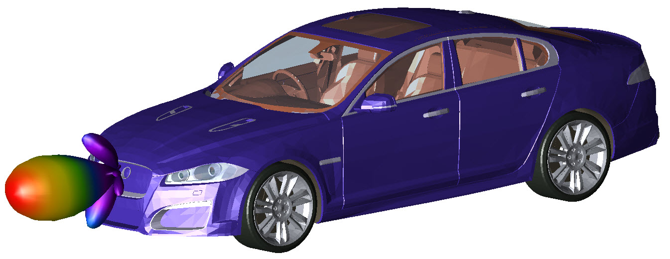
Radiation pattern for a Long Range Radar sensor.
Time-Domain EM Simulation
Full wave EM simulators generally fall into two categories – frequency or time-domain – based on what form of Maxwell’s equation the simulator solves. FDTD is a first principles technique that directly solves Maxwell’s time-dependent curl equations – Ampere’s and Faraday’s laws – by discretizing both time and space. During a simulation, the time-domain signal is analyzed as it moves through the simulation structure’s mesh at time steps that are based on geometric feature size.
Both types of microwave EM simulators provide frequency-domain outputs such as S-parameters, E and H fields, and far-field antenna radiation patterns. FDTD accomplishes this using a Fourier transform on time-domain data. FDTD also allows users to simulate time-domain excitation signals and responses including time-domain reflectometry (TDR).
Time-Domain Reveals Source of Coupling
The analysis of unwanted coupling and cross talk – fundamental to high frequency printed circuit board signal integrity (SI) analysis – typically looks at port quantities related to the nets or signal traces. The cross talk might be expressed in terms of S-parameters or visualized as heat maps of frequency-domain field distribution. These types of results allow one to verify that a problem exists, but they do little for identifying the root cause.
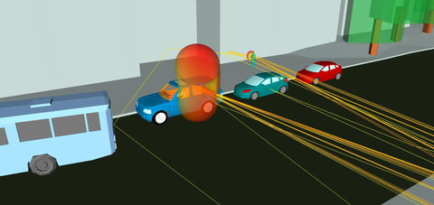
With FDTD analysis, one can watch the coupling occur. In Figure 1, a time-domain signal is applied at the top of the microstrip (region with red fields). As designed, the signal travels down the trace and to the left. Unexpectedly, the signal also travels across the ground plane and couples to another trace (top left of the source). Visualizing the steady state result in frequency-domain would verify coupling, but it does not identify the exact coupling path that is clearly visible in time-domain. For an automotive radar circuit, with multiple traces feeding arrays of antenna elements, the ability to identify one specific coupling path among many possible paths is crucial to consistently achieve successful designs.
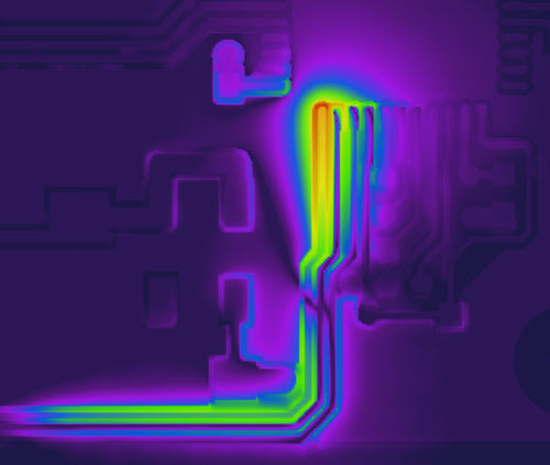
Figure 1: Fields unexpectedly couple across the ground plane to a nearby trace.
Memory Requirements for Electrically Large, Complex Models
24 GHz and 77 GHz automotive radar circuits and antennas have wavelengths in the range of 1.25 cm and 0.4 cm, respectively. EM simulation scales to wavelength and feature size, with typically 10-20 mesh elements per wavelength. An entire automotive radar sensor – including a fully detailed RF circuit board, radome, data connector, and case – is electrically large and leads to a large simulation mesh. For an FEM simulation, the tetrahedral mesh can become very complex which leads to huge matrices that require very large amounts of computer memory to solve.
FDTD EM simulation allows simulation of these complex models because the FDTD computation time grows linearly, or somewhat more than linearly, with increasing problem (mesh) size1. As a result, a simulation containing a fully detailed 25 GHz sensor and piece of fascia requires less than 8 GB of RAM. In the context of system simulation, using FDTD simulation means high fidelity; it isn’t necessary to make simplifications to the design that trade away simulation accuracy in order to reduce memory requirements.
GPUs Accelerate FDTD Simulation
In addition to handling electrically large simulations with a minimal amount of RAM, FDTD can simulate those structures quickly utilizing graphics processing units (GPUs). A GPU is a piece of computer hardware that contains RAM and processors, similar to a CPU. Unlike a CPU with a few cores, however, a GPU can have thousands. For example, the NVIDIA K40 has 2,880 cores. This massively parallel processing power has caused GPUs to gain popularity for many high performance computing (HPC) applications.
Not all EM formulations benefit from the parallel processing power of a GPU. In FEM analysis, the unstructured mesh is stored in sparse matrices and an additional level of indirection is required to map adjacent spatial element locations to memory addresses during matrix inversion operations. This obstructs the effectiveness of parallel processing and limits speedups to roughly 5x. In contrast, the FDTD mesh and field data are stored in highly structured arrays in memory. This enables the GPU to efficiently parallelize the FDTD computation and access the electric and magnetic field data. As a result, FDTD simulations run 40x faster when comparing a GPU to a CPU for the benchmark of a 25 GHz automotive radar sensor.
Conclusion
FDTD is the preferred simulation method for automotive radar sensor design because it is able to solve electrically large, complex models with minimal RAM requirements. Coupled with GPU acceleration, engineers are able to get results in hours and more efficiently identify locations where design improvements are needed. In the end, FDTD expands the EM simulation capability available to automotive radar circuit and systems level designers.
References:
1. “Microwave Circuit Modeling Using Electromagnetic Field Simulation” by Daniel G. Swanson, Jr. and Wolfgang J. R. Hoefer, copyright 2003 Artech House ISBN 1-58053-308-6 page 155