 This example consists of a half-wave vertical dipole at 300 MHz inside a corner reflector as shown in Figures 1 and 2. The corner reflector is formed from three orthogonal plates which are five meters (five wavelengths at 300 MHz) on a side. The center of the vertical dipole is above the center points of all three plates. This puts the feed of the dipole at 2.5 wavelengths from each plate. Three variations on this test case have been modeled.
- Perfectly conducting thin metal plates
- Perfectly conducting metal plates covered with a 14 cm thick lossy dielectric coating (relative permittivity = 4, conductivity = 0.1 S/m) on both sides
- 28 cm thick dielectric plates (relative permittivity = 4, conductivity = 0.05 S/m).
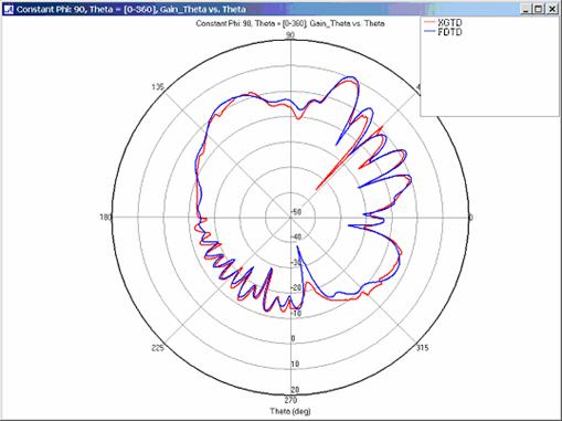
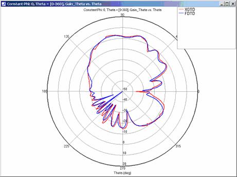
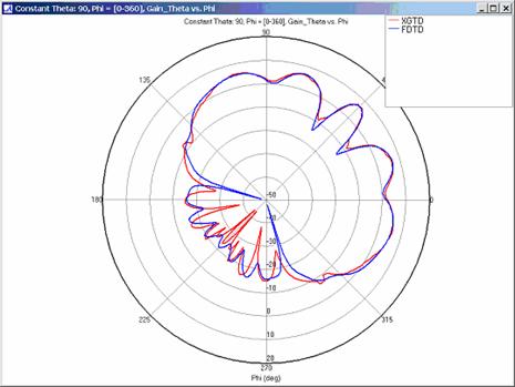
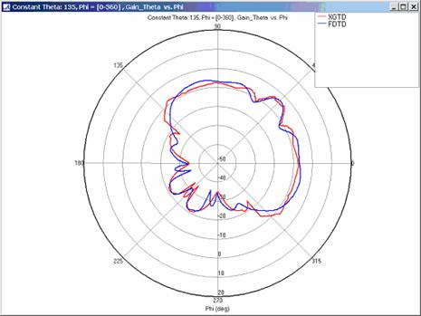
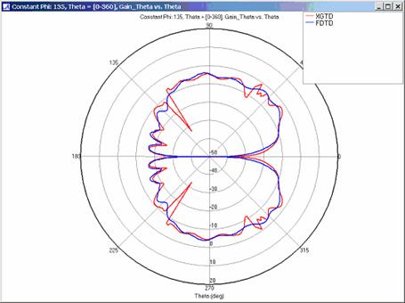
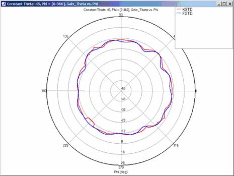
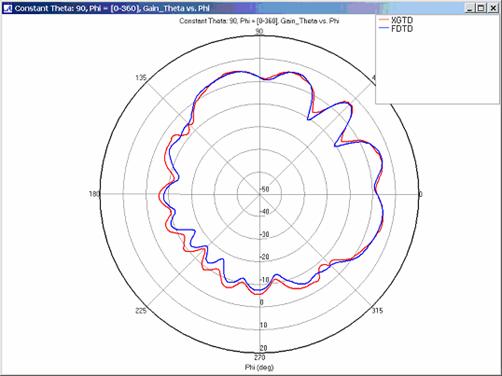
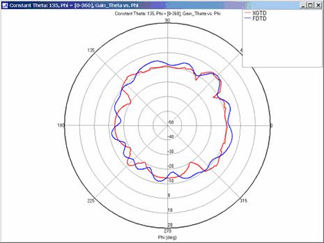
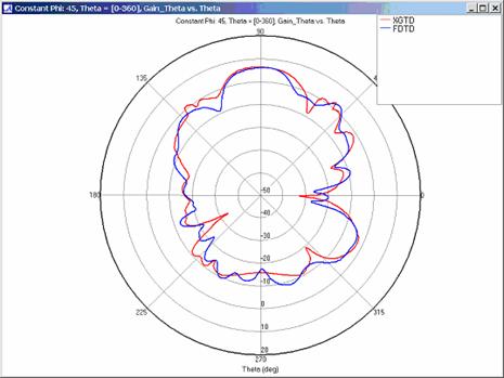
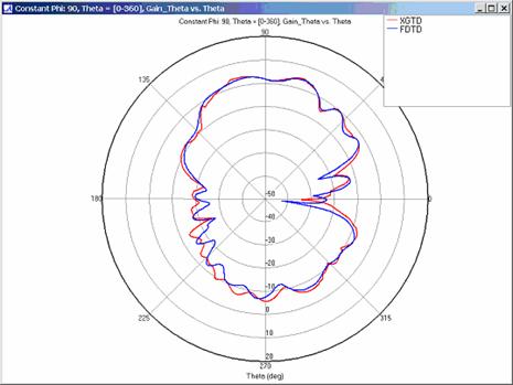
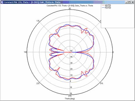
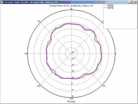
XGtd's far zone capability allows the antenna gain in dBi to be calculated on circles of constant polar angle theta, or constant azimuth angle phi, where the angles theta and phi are defined using the conventional spherical coordinate system (see Figure 3). The theta polarized gain are compared on seven circles, four circles of constant phi = 0, 45, 90, 135 deg., and three circles of constant theta = 45, 90, 135 deg. The XGtd far zone gain results are compared to FDTD calculations made using a cell size of 5.556 cm (18 cells/wavelength at 300 MHz).
Figure 1 shows the corner reflector geometry. Each plate measures five wavelengths on a side at 300 MHz. The dipole (not shown) is located 2.5 wavelengths above the center points of the plates. The dipole is a half-wavelength long at 300 MHz.
In Figure 2, the green box indicates the position of the center of the dipole. The vertical white line is only included for reference and is not part of the model.
Figure 3 shows the spherical coordinate system used in XGtd.
Far Zone Antenna Gain Results for Metal Plates
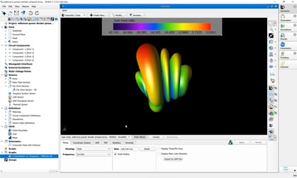
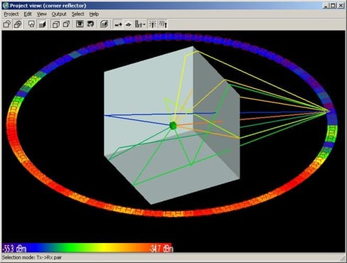
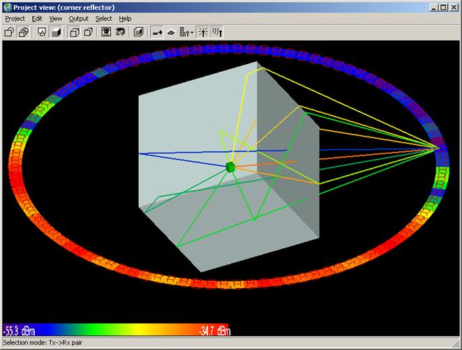
Far zone and received power results for the corner reflector made from perfect electrical conducting metal plates were calculated using XGtd's Full 3D model with a maximum of 2 reflections and 1 diffraction. The received power for a horizontal arc of receivers along with propagation paths to a receiver on the arc are shown in Figure 4. Far zone results are compared to full wave FDTD results in Figure 5, Figure 6, Figure 7, Figure 8, Figure 9, Figure 10, and Figure 11.
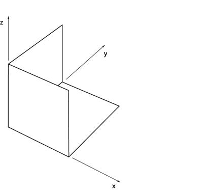
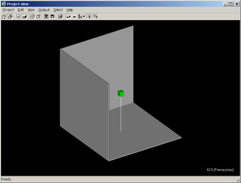
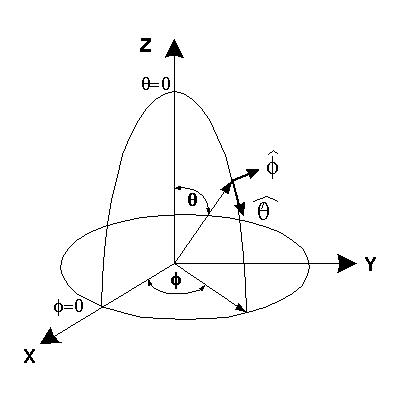
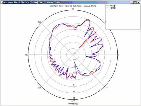
Figure 5
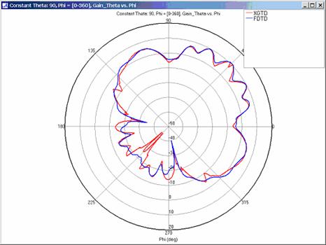
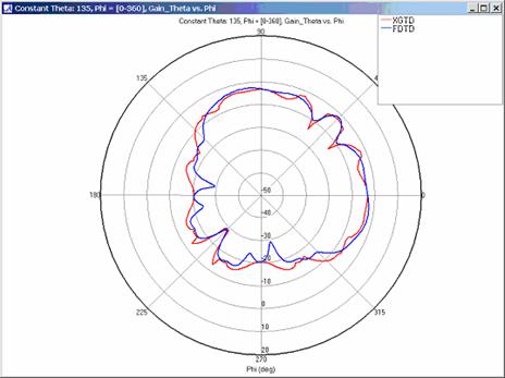
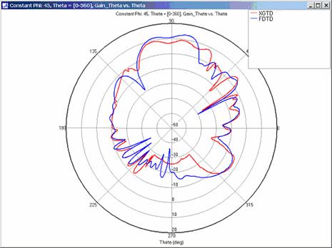
Figure 8
Far Zone Antenna Gain Results for Lossy Coated Metal Plates
XGtd implements a modified version of UTD that extends the applicability of UTD beyond perfectly conducting metal surfaces. This portion of the example exhibits XGtd's ability to model reflections and diffractions for plates coated with a lossy dielectric layer. Far zone and received power results for the corner reflector were calculated using XGtd's Full 3D model with a maximum of 2 reflections and 1 diffraction. The received power for a horizontal arc of receivers along with propagation paths to one of the receivers on the arc are shown in Figure 4. Far zone results are compared to full wave FDTD results in Figure 13, Figure 14, Figure 15, Figure 16, Figure 17, Figure 18, and Figure 19.
Far Zone Antenna Gain Results for Lossy Dielectric Plates
Modeling a corner reflector composed of lossy dielectric plates increases the complexity of this example. In addition to modeling reflections and diffractions with a lossy material, accurate modeling of transmissions through the dielectric plates is necessary to obtain the correct far zone results. Far zone antenna gain and received power were calculated using XGtd's Full 3D propagation model with 2 reflections, 1 transmission, and 1 diffraction. The received power for a horizontal arc and rays paths to a single receiver along the arc are shown in Figure 20. The transmission of energy through the lossy dielectric plate is clearly seen in this figure. Far zone results are compared to FDTD results in Figure 21, Figure 22, Figure 23, Figure 24, Figure 25, Figure 26, and Figure 27.

Conclusion
For all three cases, XGtd's far zone antenna gain results show good agreement with the full wave FDTD results. The general shape and magnitude of the pattern is captured in the XGtd solution. Differences between the patterns exist because XGtd only includes the effects of paths that undergo a maximum of 2 reflections, 1 diffraction, and 1 transmission (for the dielectric plate case). FDTD directly solves Maxwell's equations and therefore includes all relevant interactions provided the geometry is represented by a mesh with sufficient resolution. Even by only considering paths with a maximum of 2 reflections and 1 diffraction, XGtd closely matches the FDTD results indicating these paths are the primary contributors to the far zone fields.