In this simple example, a basic air-filled parallel plate capacitor is constructed in XFdtd by making two perfectly conducting plates of size 20x20 mm separated by a gap of 2 mm. The two plates are then connected by a loop of wire as shown in Figure 1. On the upper and lower parts of the loop are 50 ohm resistors for dissipating the transient currents in the circuit. At the side of the loop is a 1 A current source excited by a Gaussian pulse waveform. This source is activated in the simulation and the resulting current flow in the wire charges the plates until a steady state condition is reached.
Figure 1: The structure of the air-filled parallel plate capacitor as modeled in XFdtd.
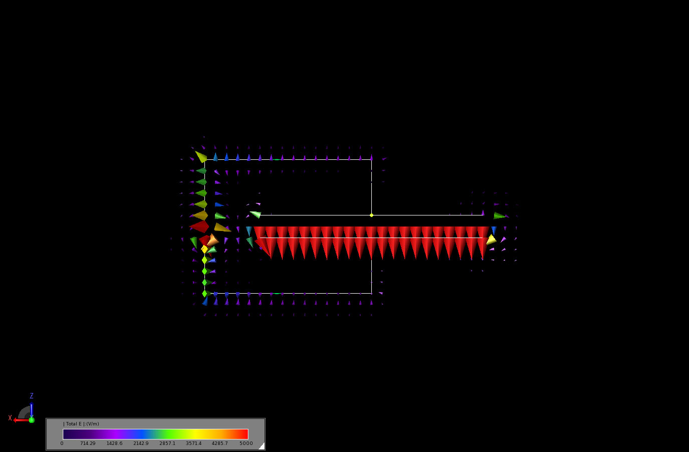
The transient response of the simulation can be demonstrated by viewing the electric fields at a few instances in time. In Figure 2, the current source has just begun the pulse and the electric fields in vector form can be seen around the source. In Figure 3 the current has reached the plates and fields can be seen growing between the plates. In Figure 4 the current has returned back around to the source while the fields between the plates are growing in strength and other fields are radiated off the circuit. By Figure 5 all transients have dissipated and the static fields between the plates have been established with a strength of about 5000 V/m between the plates.
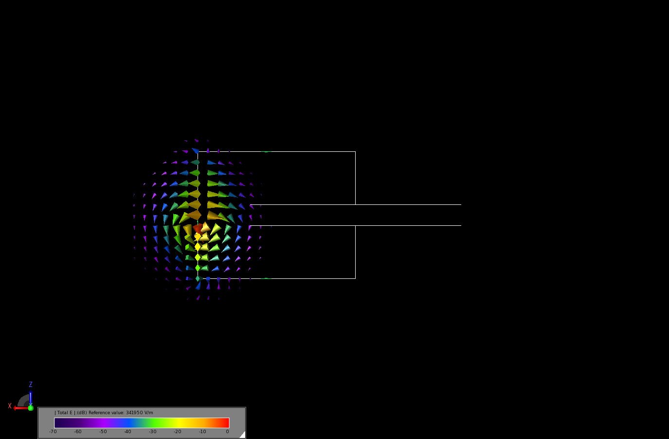
Figure 2: The vector display of the transient electric fields through a plane of the capacitor at an early stage of the simulation, when the current just begins to flow from the source.
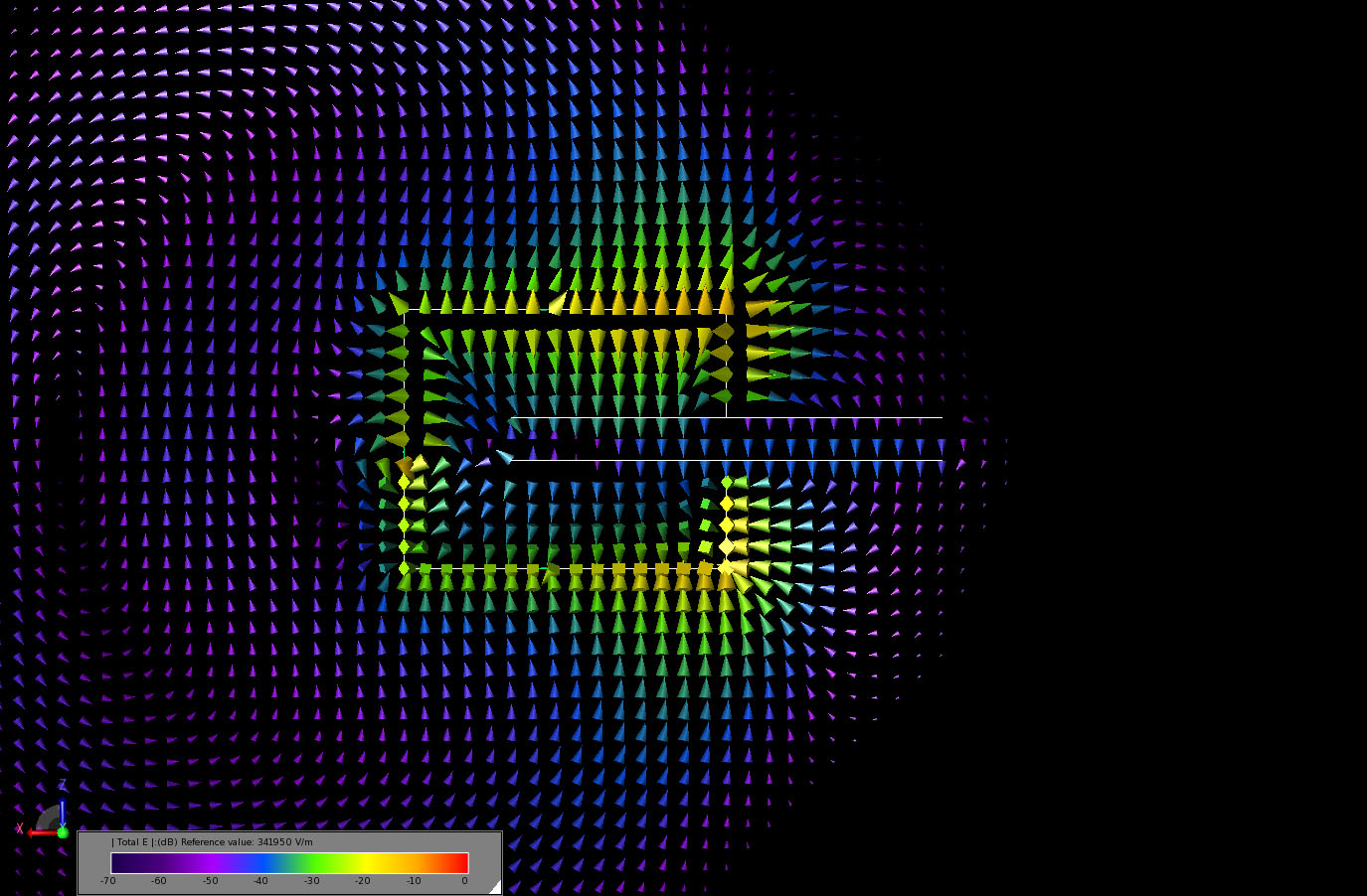
Figure 3: The vector display of the transient electric fields through a plane of the capacitor as the current just reaches the parallel plates.
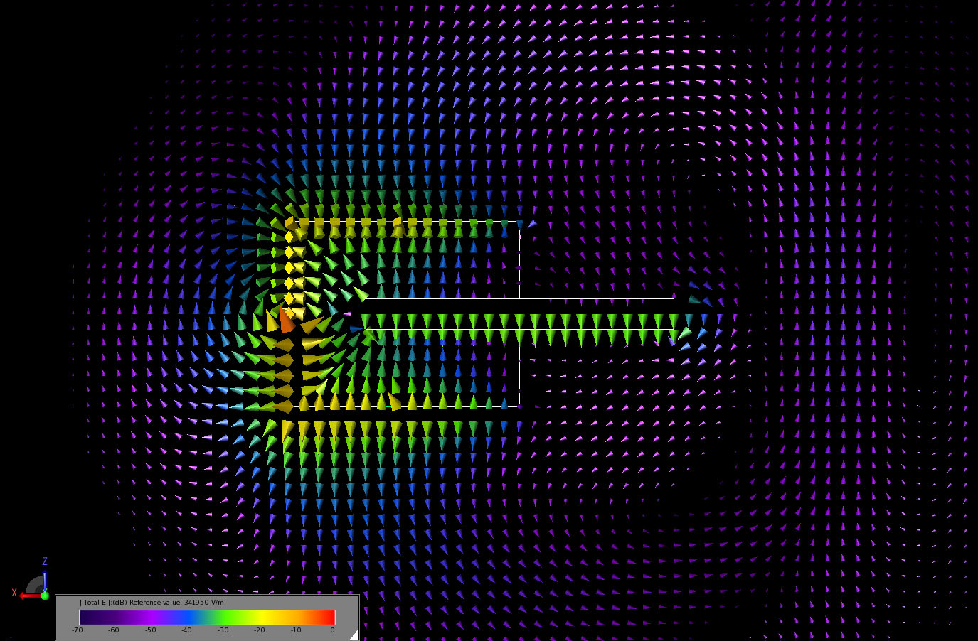
Figure 4: The vector display of the transient electric fields through a plane of the capacitor as the current circulates back to the source and the transient fields are radiated and dissipated.
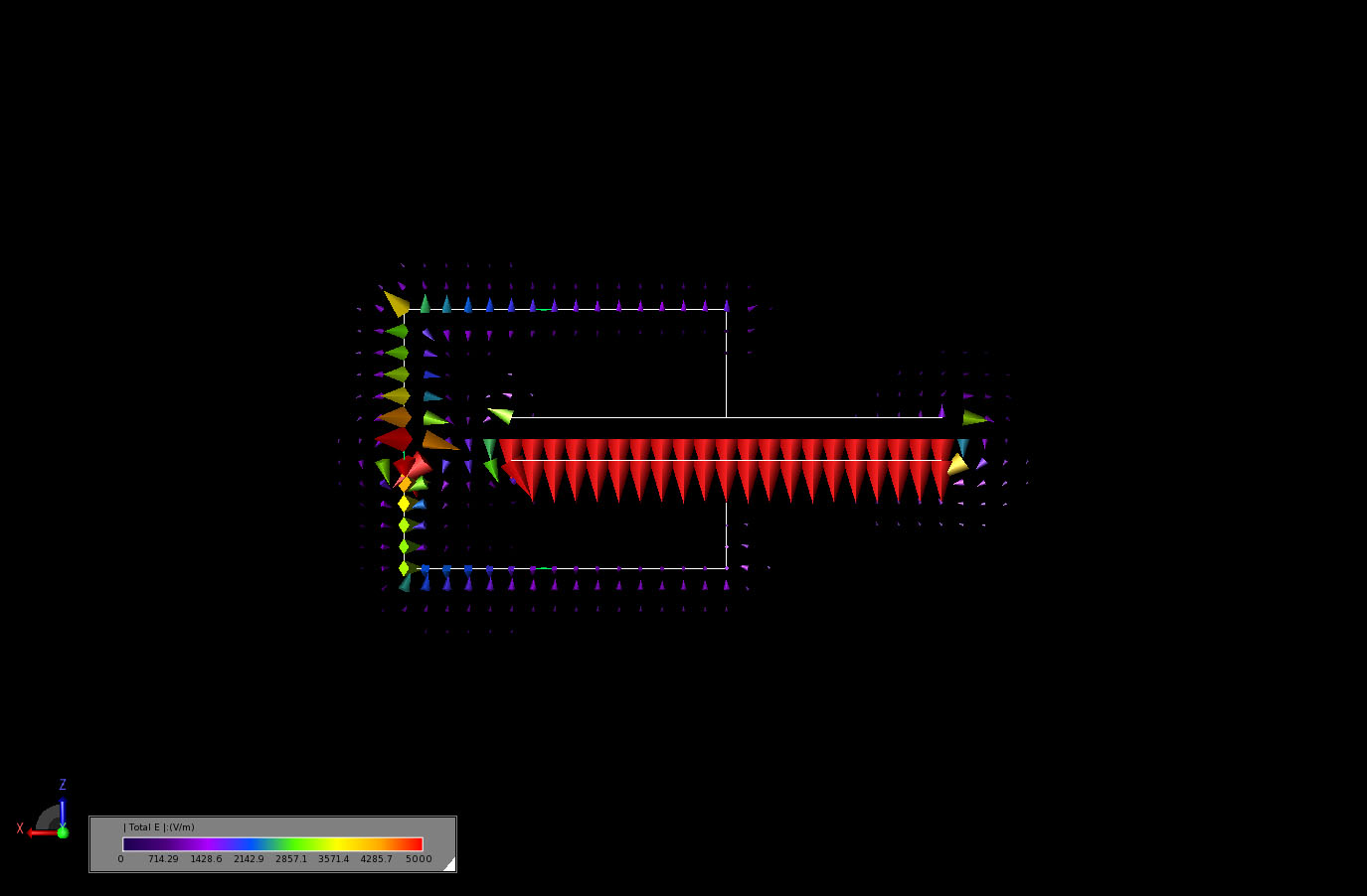
Figure 5: The vector display of the transient electric fields through a plane of the capacitor after the circuit has reached steady state and the plates are fully charged. In this figure the scale has been changed to show volts/meter rather than a dB scale.
Alternatively, this charging simulation could be set up using the static solver in XFdtd. This solver allows the user to apply preset voltage levels to different parts of the geometry. The steady state static fields are then found by solving Laplace's equation at each FDTD mesh edge in the geometry. In this example, the top of the capacitor has a voltage of +5 V applied while the bottom plate has -5 V. Following the Laplace solution, the fields established can be seen to be nearly identical to those generated by the current source simulation. This can be observed by comparing Figure 5 (current source simulation at steady state) to the Figure 6 (Laplace static solution). In a different application, the static fields might be desired before a simulation and then a transient field might be applied.