Learn more about our antenna simulation software…
Introduction
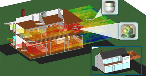
The connected home concept includes many “smart” aspects including speakers, thermostats, doorbells, and cameras. This example discusses the performance, as simulated by XFdtd EM Simulation Software, of a generic remote camera that provides video surveillance around the house for security monitoring. The camera is intended to connect to a WiFi system that covers the 802.11 a/b/g/n/ac/ax standards at frequencies of 2.4, 5, and 6 GHz and includes two multiband conformal antennas that transmit the high-resolution video.
Device Design and Simulation
The generic camera design uses two conformal multiband antennas that wrap around the interior surface of the camera housing. The antennas are designed to provide coverage at 2.4, 5, and 6 GHz and can be phased to steer the antenna patterns for maximum coverage. In addition to the antennas, there are mounting structures, PCB boards, camera imaging chips and the lens, which are represented by block parts in this simple model. A three-dimensional CAD view of the camera is shown in Figure 1, where one of the antenna elements is visible through the translucent case of the camera. The entire camera fills a space of about 70x70x70 mm. In Figure 2, a more detailed view of one of the antenna elements shows the curvature of the element to conform to the interior wall of the camera case. The antenna has been tuned to provide reasonable return loss of less than -10 dB at the desired frequencies of 2.4, 5, and 6 GHz as shown in Figure 3. The curving of the antenna to fit into the case has a significant impact on the performance of the antenna and makes tuning of the antenna in its final configuration a necessity.
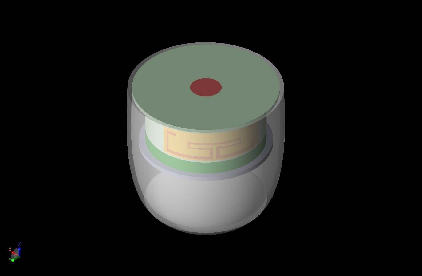
Figure 1: A three-dimensional view of a generic remote camera device is shown with the internal antenna arrays partially visible through the cover.
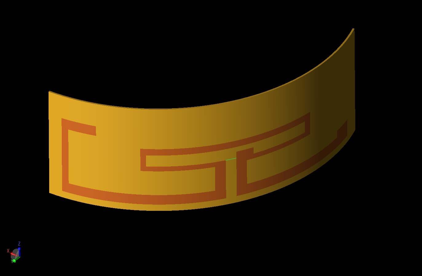
Figure 2: One of the two identical multiband antennas in the remote camera.
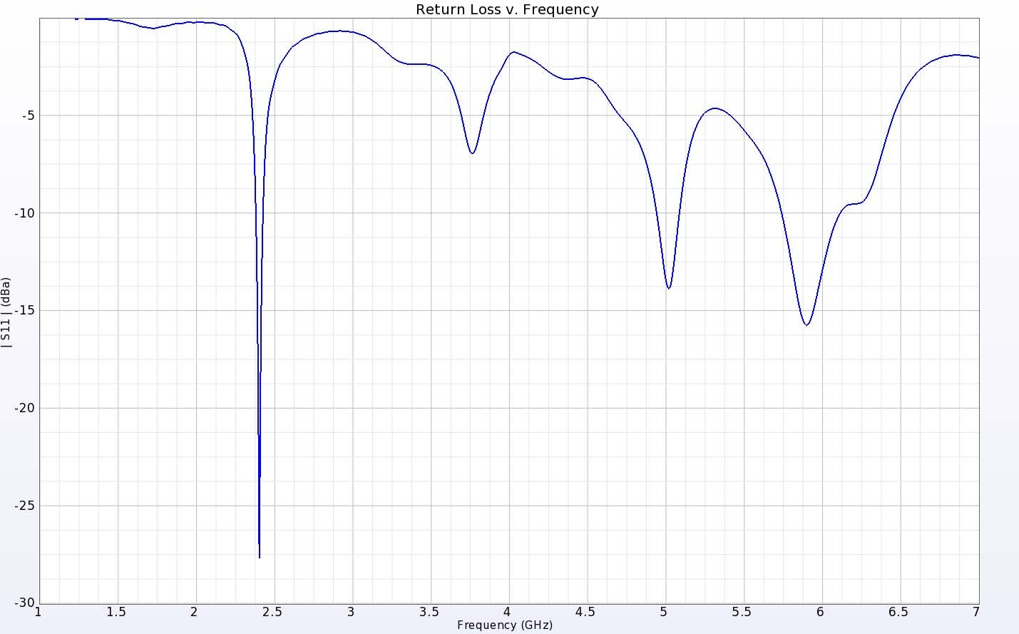
Figure 3: The return loss for the multiband antenna shows good performance at 2.4, 5 and 6 GHz as desired.
The gain patterns of the antennas have coverage focused to the sides and forward of the camera. The patterns of the two antennas operating independently are shown at 2.4 GHz in Figure 4, at 5 GHz in Figure 5, and at 6 GHz in Figure 6, where the front of the camera with the lens is facing the viewer in all of the images. The peak gain of the individual elements ranges from about 3 dBi at 2.4 GHz to nearly 7 dBi at 5 GHz. At 2.4 GHz the pattern is quite broad, while at the higher frequencies the pattern is more complex with some lobes.
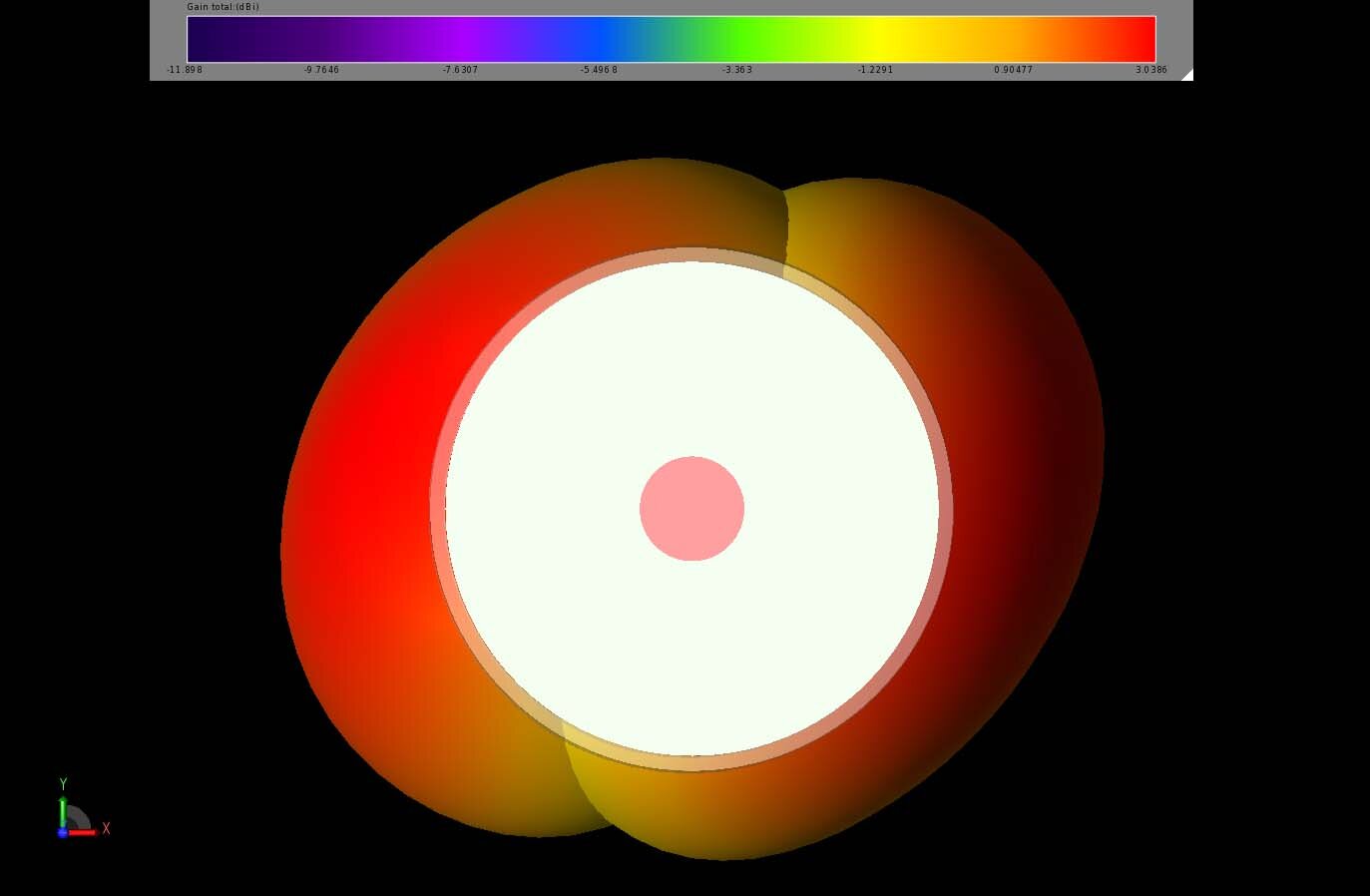
Figure 4: The gain patterns of the two antennas at 2.4 GHz show two broad lobe patterns covering half of the device. The orientation of the image is looking directly at the front of the camera.
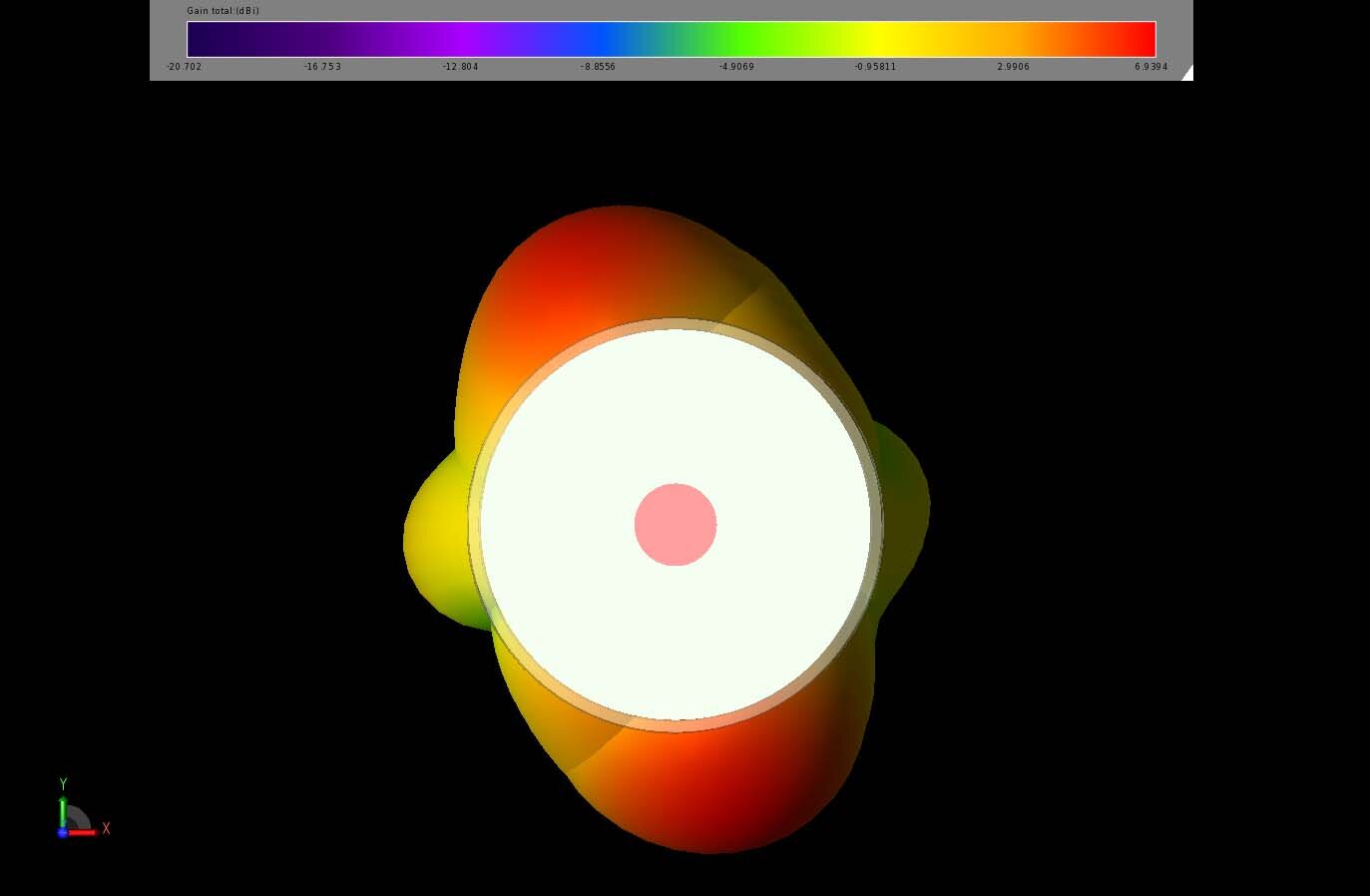
Figure 5: The gain patterns of the two antennas at 5 GHz show two narrower patterns with high gain normal to the antenna. The orientation of the image is looking directly at the front of the camera.
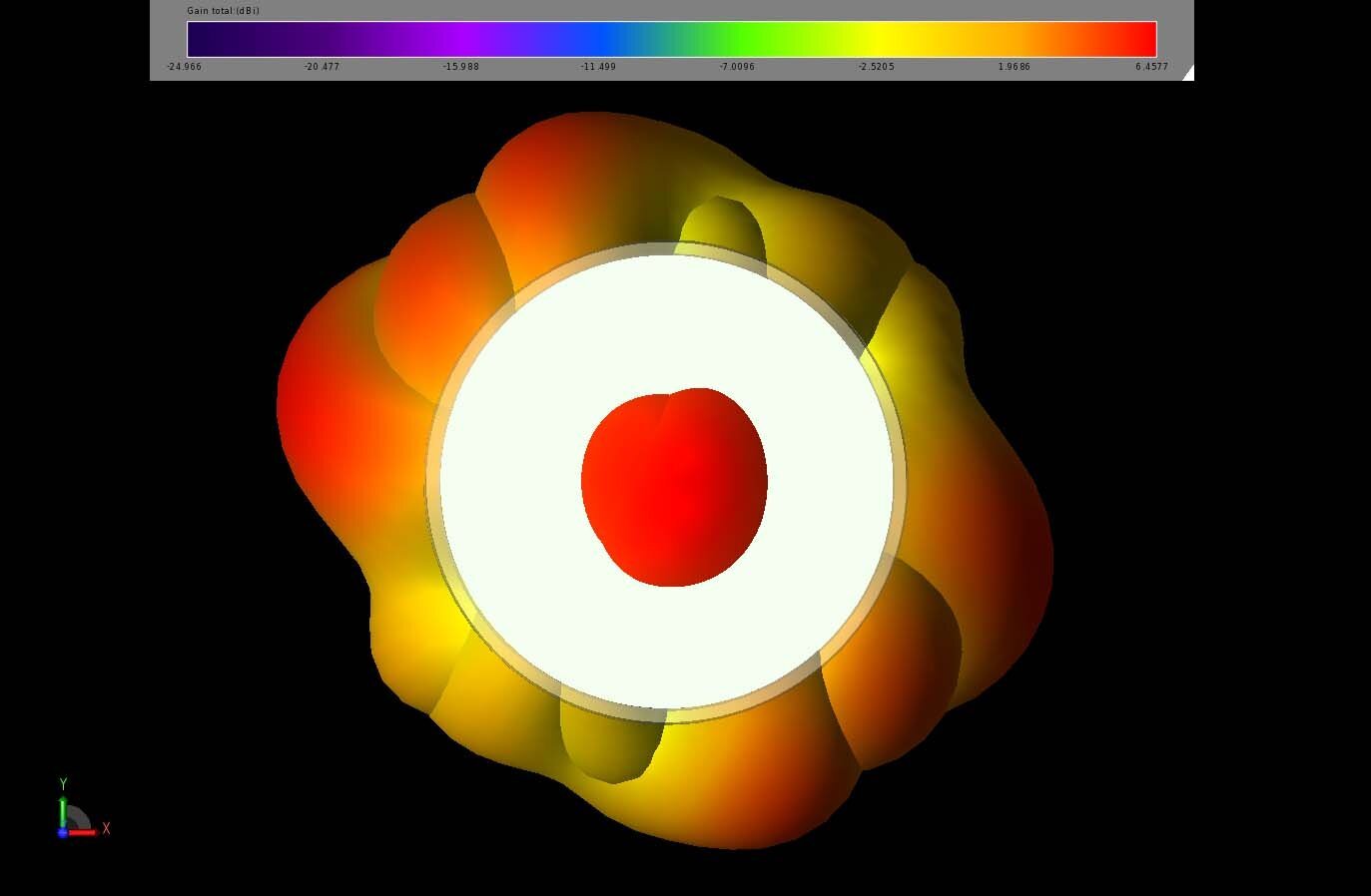
Figure 6: The gain patterns from the two antennas at 6 GHz show multi-lobed patterns which cover most of the azimuthal plane of the device and have a lobe pointed in the forward direction of the camera. The orientation of the image is looking directly at the front of the camera.
Since the camera could be mounted in a random orientation, it is desirable to have coverage over the full range of angles. However, as there are some internal parts in the generic camera such as the PCB boards and support structures, the gain to the rear of the camera is reduced. Using the array optimization features in XFdtd, the performance of the arrays can be determined to find the full coverage possible. In Figure 7 the Max Hold pattern is computed for the two antennas at 2.4 GHz, which shows good gain in the forward direction and around the azimuthal plane. In Figure 8, the Max Hold pattern at 5 GHz shows strong lobes to the sides of the antenna and reduced, but positive, gain in the forward direction. At 6 GHz, shown in Figure 9, the Max Hold pattern shows strong gain in the forward direction and lower gain to the sides. Figures 7, 8, and 9 show the patterns with the camera oriented as shown in Figure 1.
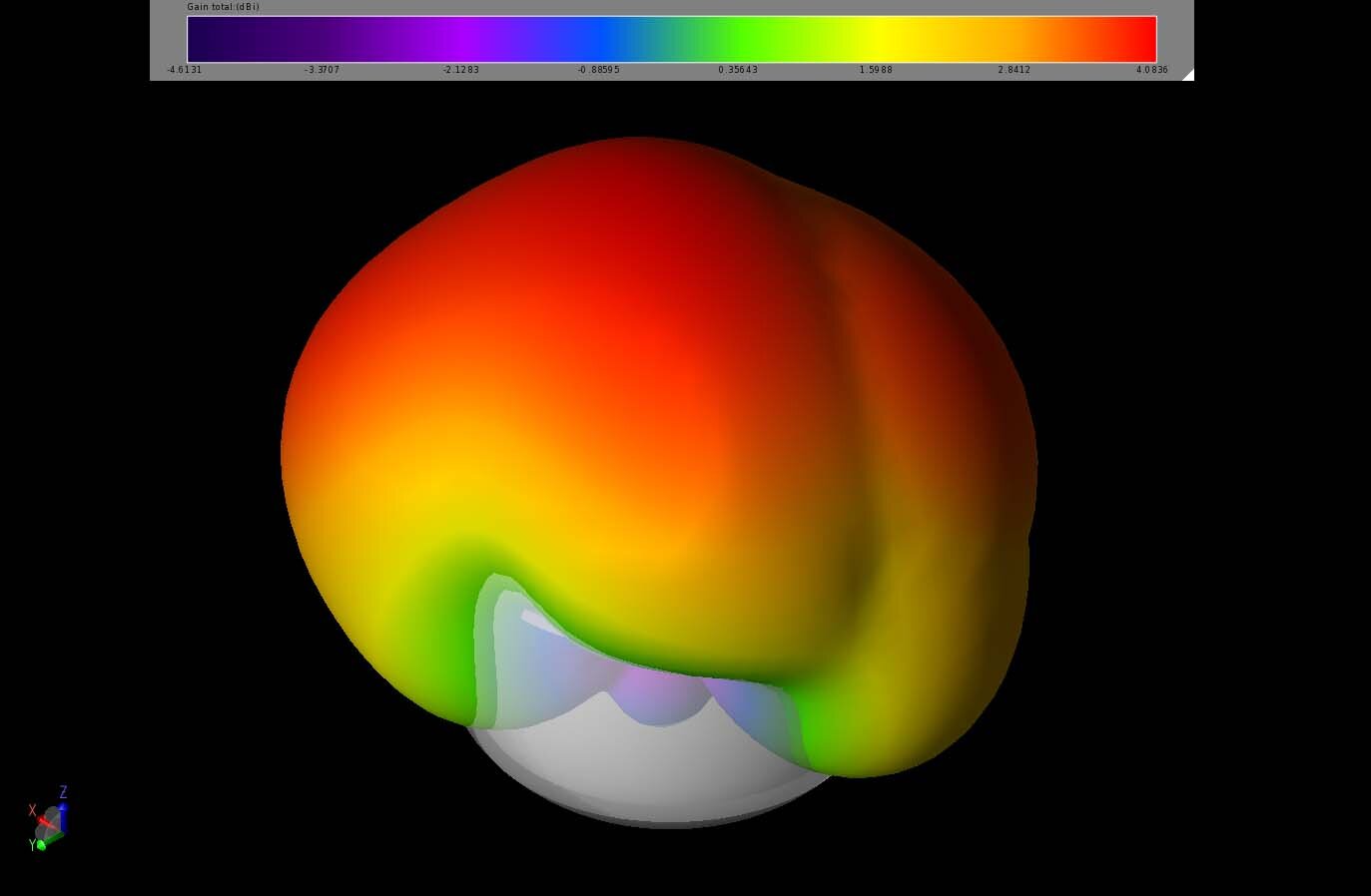
Figure 7: The Maximum EIRP pattern of the two antennas at 2.4 GHz shows broad coverage over the forward region of the camera. The orientation of the camera in the image is identical to that shown in Figure 1.
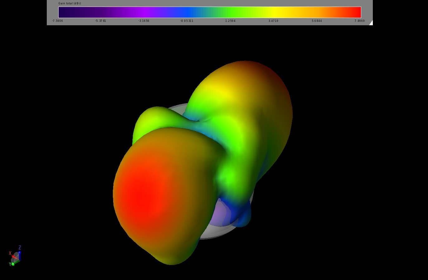
Figure 8: The Maximum EIRP pattern of the two antennas at 5 GHz shows high gain coverage normal to the antenna plane in the azimuthal direction. The orientation of the camera in the image is identical to that shown in Figure 1.
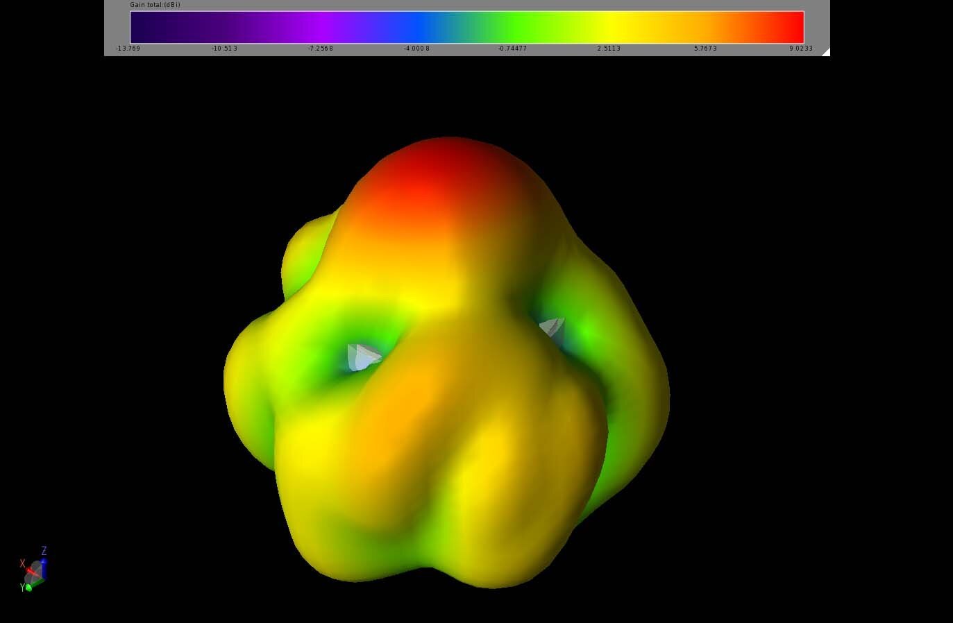
Figure 9: The Maximum EIRP pattern of the two antennas at 6 GHz shows a strong gain in the forward direction and nearly even coverage in the azimuthal direction. The orientation of the camera in the image is identical to that shown in Figure 1.
By creating a cumulative distribution function of the EIRP, it is possible to compute the maximum coverage over the full three-dimensional sphere surrounding the device. In Figure 10, the CDF of EIRP plot shows that for all possible phasing relationships of the elements at 2.4 GHz, positive gain is possible for about 67% of the directions. At 5 GHz, the CDF plot shown in Figure 11 has just over 60% coverage with positive gain. Finally, at 6 GHz, Figure 12 shows nearly 70% of the directions may have positive gain.

Figure 10: The CDF of EIRP plot for the two antennas at 2.4 GHz shows positive gain for about 67% of the directions.
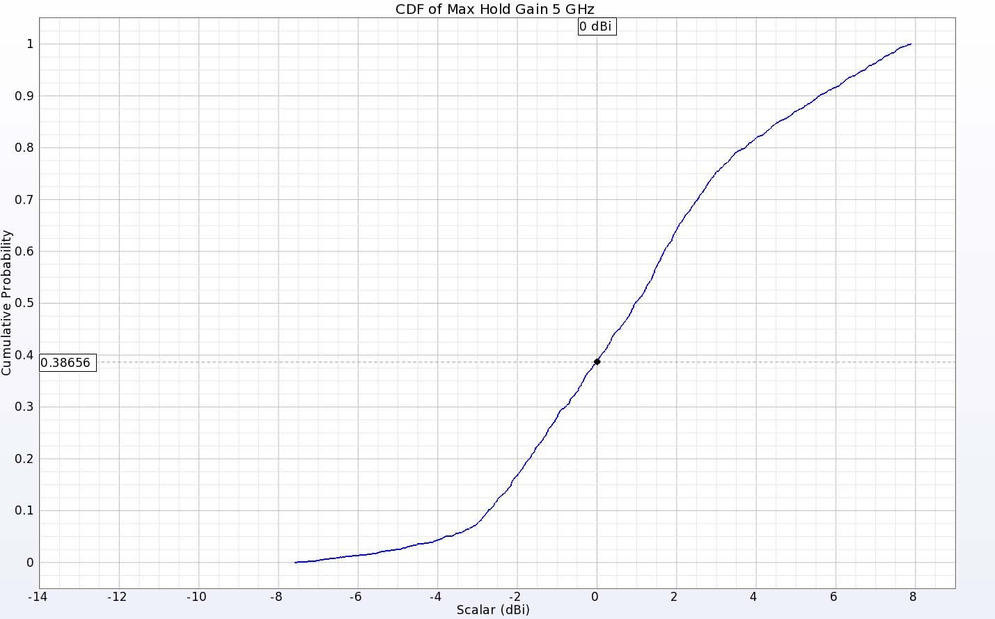
Figure 11: The CDF of EIRP plot for the two antennas at 5 GHz shows positive gain for about 60% of the directions.
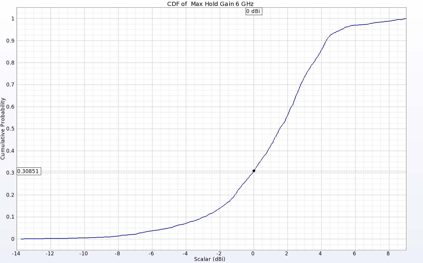
Figure 12: The CDF of EIRP plot for the two antennas at 6 GHz shows positive gain for about 70% of the directions.
Conclusion
Maintaining good contact with a remote device such as a camera is a critical feature of any connected home system. This generic camera design has been evaluated with XFdtd and found to have at least positive gain for over 60% of directions at three frequencies with peak gain as high as nearly 7 dBi. This should provide adequate connectivity for most installation configurations.