The patch antenna is 20 mm (across chest direction) by 32 mm (head to foot direction) with a substrate of lossless dielectric of permittivity 9.5. The patch is 2 mm thick with the ground plane and patch radiator the same dimensions. The patch feed is offset from the center of the patch in the vertical (long) dimension.
Initial calculations are for the patch antenna in free space. In anticipation of using a 2 mm human body mesh, the patch is initially meshed with 2 mm FDTD cells. A 3D rendering of the mesh shows the offset feed location in Figure 1. All calculations are at 2.45 GHz.
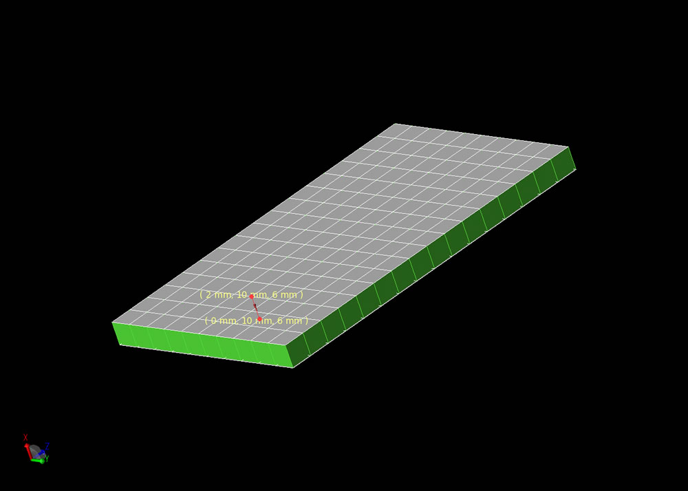
Figure 1: Mesh representation of patch antenna showing offset feed.
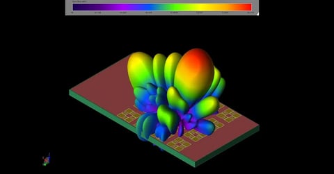
Initial calculations made for the patch antenna in free space found an input impedance of 0.025 + j 11.8 Ohms with 100% efficiency. The radiation gain pattern with respect to an isotropic antenna for the horizontal plane is shown in Figure 2. The blue line is for E theta (vertical) polarization and the red line is for E phi (horizontal) polarization.
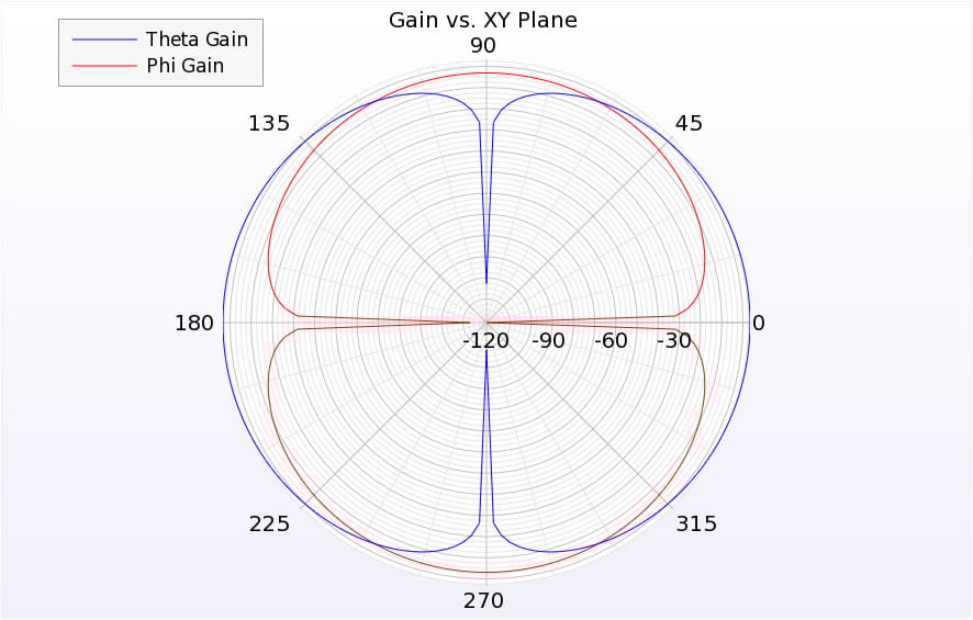
Figure 2: Far zone gain of patch in free space.
The near zone transient electric fields in the plane of the patch antenna are shown in the Figure 3. Near zone steady state electric field is displayed in Figure 4.
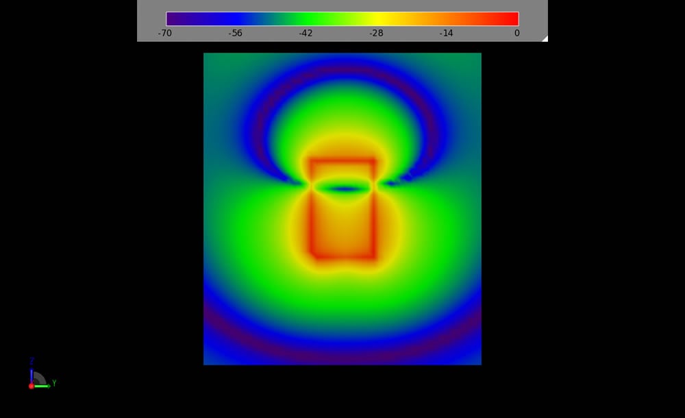
Figure 3: Time domain electric fields.

Figure 4: Steady state frequency domain electric fields.
Next a 2 mm human body mesh obtained using VariPose is imported into XFdtd as a mesh object and the patch antenna is inserted into the body mesh. Figure 5 shows a slice through the body mesh with the patch antenna. The patch is located a few millimeters inside the chest close to the front of the body. In this figure the body is looking at the reader, that is, out of the page.
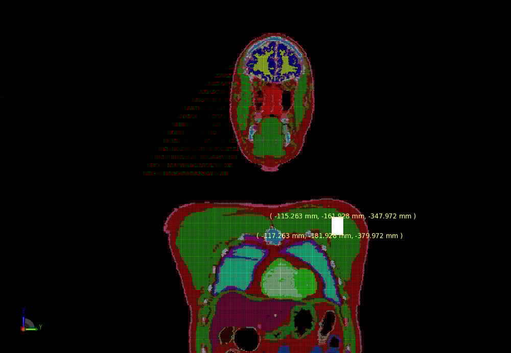
Figure 5: Mesh of the patch antenna in the body.
After the calculation is completed XFdtd finds the impedance of the patch antenna inside the human body to be 5.42 + j 19.1 Ohms with an efficiency of 0.21%. The far zone radiation pattern for the patch antenna inside the body shows the reduction in gain due to the loss in the body tissues. The body is facing toward an angle of 0 degrees with the (left) shoulder containing the patch toward an angle of 90 degrees as shown in Figure 6.
Figure 7 shows a 3D view of transient electric fields external to the body mesh.
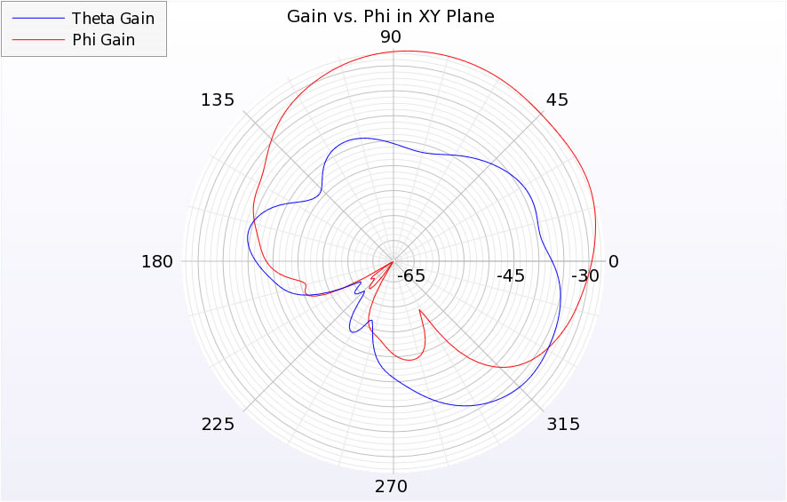
Figure 6: Far zone gain of patch in the body.

Figure 7: A slice of time domain fields through the chest.
Figure 8, Figure 9, and Figure 10 show transient electric fields in various mesh slices for the patch antenna inside the body. The CAD display of the body tissues and patch antenna is turned off to view the internal fields.
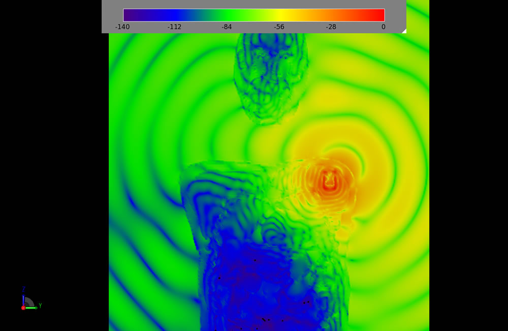
Figure 8: A slice of time domain fields through the body.
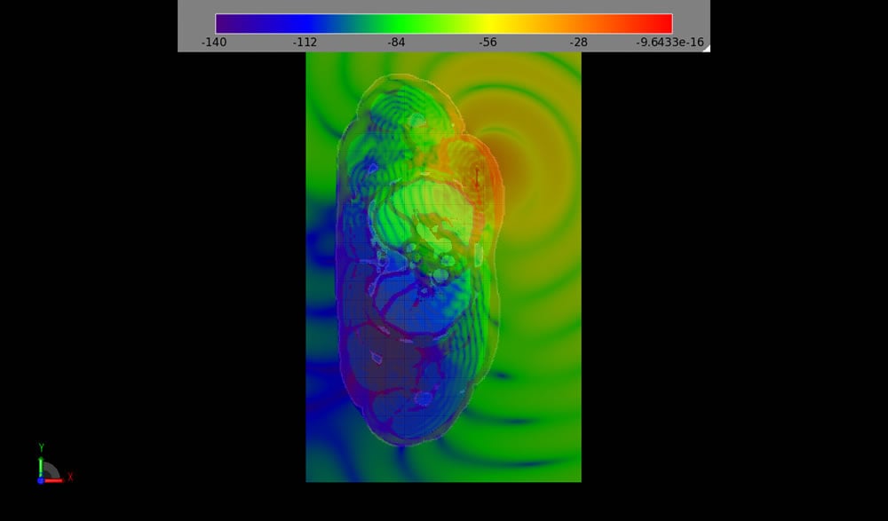
Figure 9: A slice of time domain fields through the chest (body rendering is on).
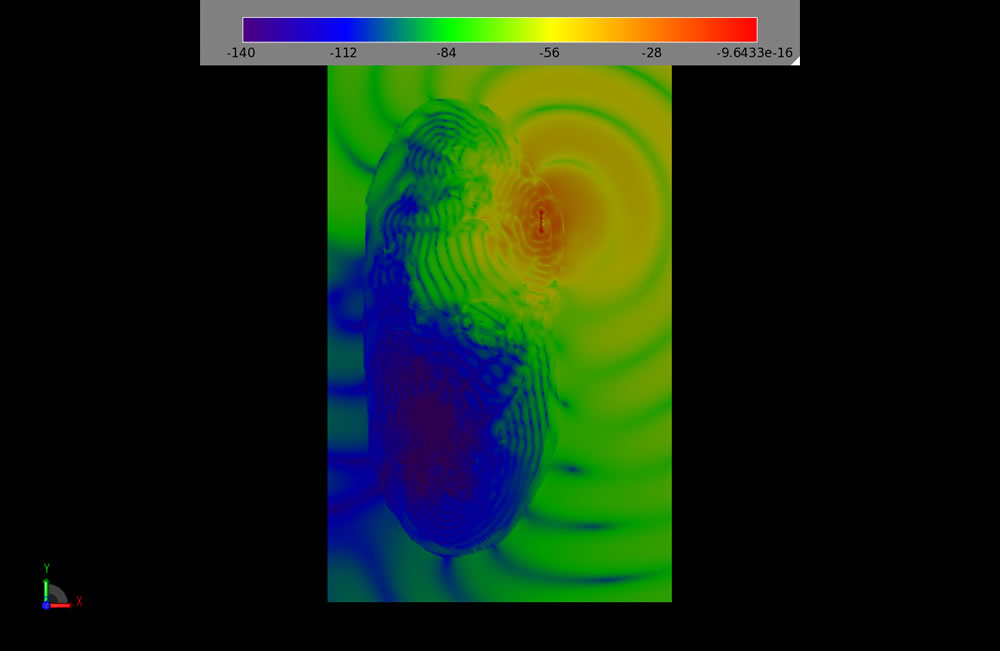
Figure 10: A slice of time domain fields through the chest (body rendering is off).
Figure 11 and Figure 12 show steady state electric fields in the plane of the patch antenna. Again, in one figure the CAD display is turned off.
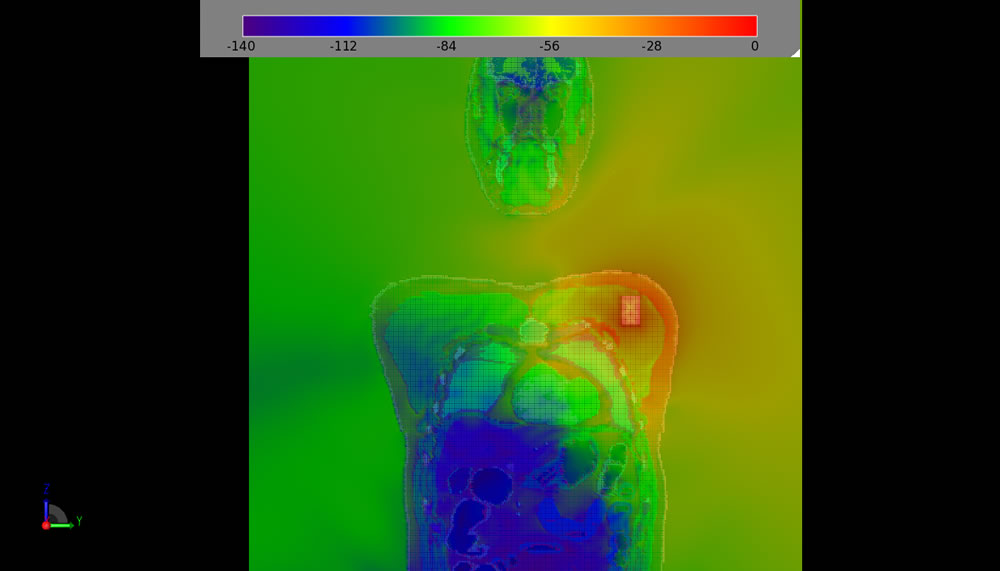
Figure 11: A slide of frequency domain fields through the chest (body rendering is on).
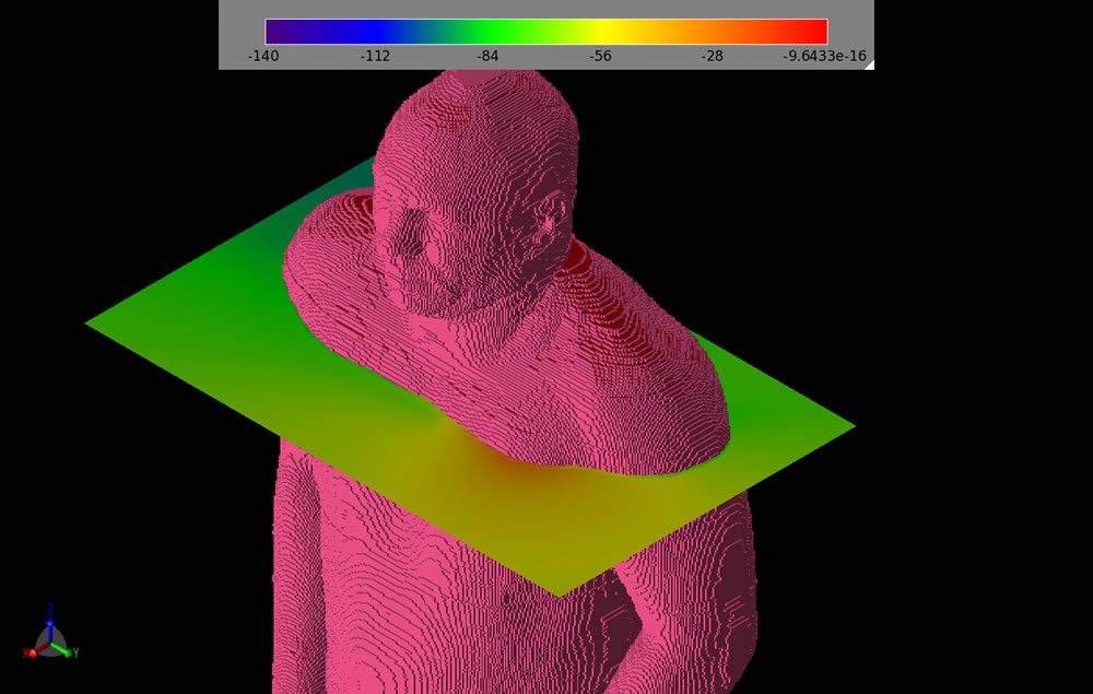
Figure 12: A slice of frequency domain fields through the chest.
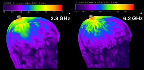
The final calculation is for Specific Absorption Rate, or SAR. In order to reduce calculation time only the chest portion of the mesh is used for the SAR calculations. A view of the chest only with near zone transient fields is shown in Figure 13.
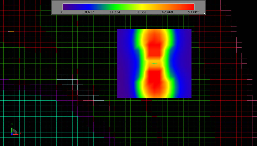
Figure 13: Automatic region of 1 gram SAR averaging around the antenna.
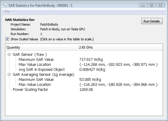
Figure 14: SAR results scaled to 1 Watt input power.
This example illustrates only the most basic application of XFdtd to this geometry. XFdtd could be used to improve the design the patch antenna in order to resonate at the desired transmission frequencies, to improve the radiation, and to reduce SAR. The effects on SAR and radiation resulting from moving the patch antenna to different locations in the body could also be investigated using XFdtd.