Results are compared with those in the paper “EMI from Cavity Modes of Shielding Enclosures - FDTD Modeling and Measurements” by Li et. al. [1]. The paper appeared in the February 2000 issue of IEEE Transactions on Electromagnetic Compatibility.
The first step in applying XFdtd to the problem is to form the box, slot, and wire geometry. The interior dimensions of the box and slot are given in Figure 1 [1] as 22 x 14 x 30 cm and 12 x 0.1 cm with the slot located 0.2 cm above the lower inside surface of the conducting box. The slotted wall of the box is 0.05 cm thick. Figure 1 was provided by Li, et al.
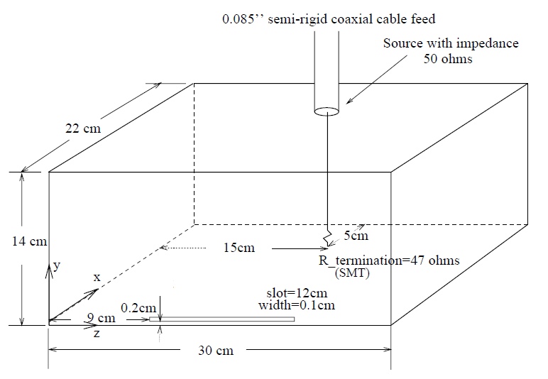
Figure 1: Schematic of enclosure and slot provided in the paper.
The hollow box was formed in XF by first creating a solid box that matches the interior dimension from the paper. A shelling operation was then applied which created five 0.635 cm thick walls and one open face. The open face was covered with a 0.05 cm thick wall and the slot was added using a Boolean Operation. Finally the inner conductor of the wire was added using an Extrude. Figure 2 is the completed model in XF.
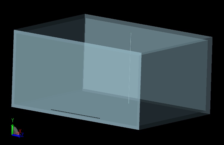
Figure 2: Model in XF.
The height of the slot and thickness of the walls can easily be resolved using XF's automatic gridding capability, which adjusts the main mesh to accurately include small features of the geometry. Minimum cell sizes were set to 0.1 cm and 0.05 cm in the directions containing the slot and thin wall and automatic feature extraction was enabled which placed grid lines at the locations of the slot and wall edges.
The model was excited by applying a broadband waveform to the voltage source located at the top of the wire. The source had a 50 Ohm resistance. At the base of the wire, a 47 Ohm resistor was placed. Finally, a broadband electric field sensor was placed along the -X axis and a simulation was run.
As a post processing step, the input waveform was scaled to match the constant 2.5 nW available power as described in the paper. Figures 3 and 4 compare the simulated results to Figure 4 [1] presented in the paper.
Figure 5 is a time domain snapshot showing the fields as they radiate outward from the thin slot.
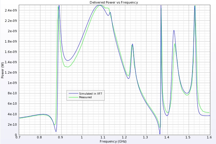
Figure 3: Comparison of delivered power vs. frequency.
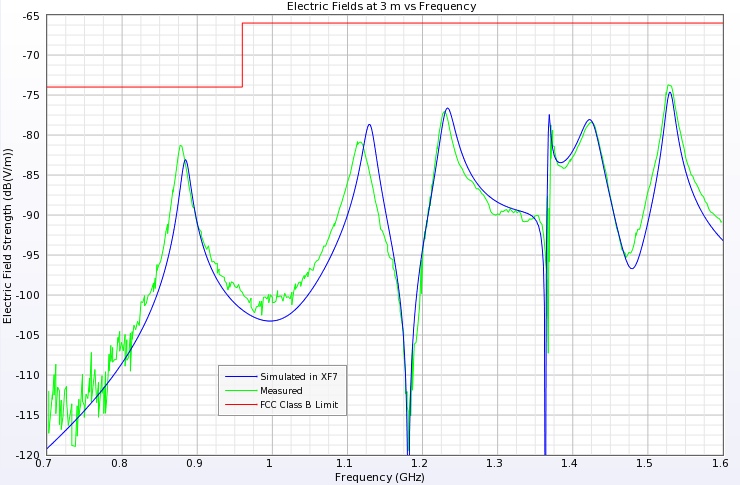
Figure 4: Comparison of electric fields at 3 meters vs. frequency.
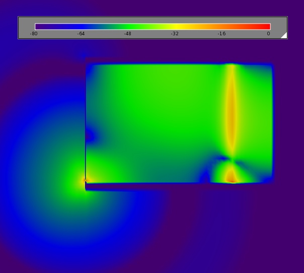
Figure 5: Time domain electric fields radiating from slot.
Reference
-
Li, Nuebel, Drewniak, DuBroff, Hubing, and Van Doren. "EMI from Cavity Modes of Shielding Encolsures - FDTD Modeling and Measurements." IEEE Transactions on Electromagnetic Compatibility, vol. 42, pp 29-38, Feb. 2000.