Correctly tuning an antenna is especially crucial for a battery powered device in order to minimize wasted power. This example takes the Dual Frequency Inverted FL Antenna, which was designed in free space, and places it inside of a netbook computer. This operating environment has a negative impact on antenna performance which is predicted by and corrected with XFdtd.
The process begins with a short investigation of the antenna itself in order to gain an understanding of how to tune it efficiently. Figure 1 shows the parameters used to specify the antenna. Surface currents are saved at three different frequencies (Figures 2-4) to identify which antenna features are worth further exploration. The parameters LL, LF, and LP are identified as good candidates, so each of these is swept over a range of values to determine how they influence the antenna. Automatic fixed points help optimize cell size usage - permitting smaller cells to be used exactly where they are needed. Each sweep can be completed in about one minute using XStream GPU acceleration. The resulting return losses are depicted in Figures 5-7.
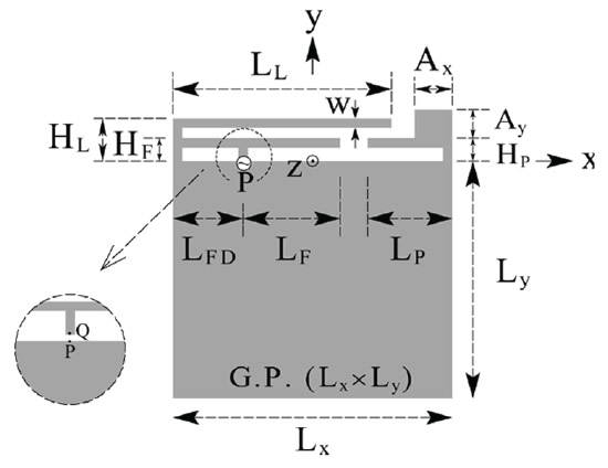
Figure 1: Antenna schematic provided in original paper.
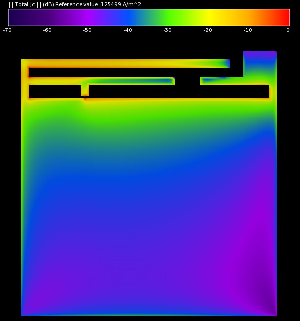
Figure 2: Surface currents on the antenna at 2.45 GHz.
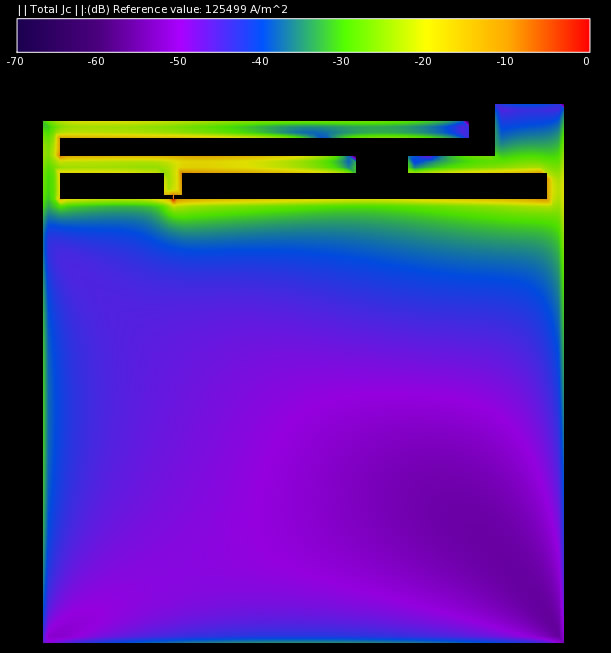
Figure 3: Surface currents on the antenna at 5.17 GHz.
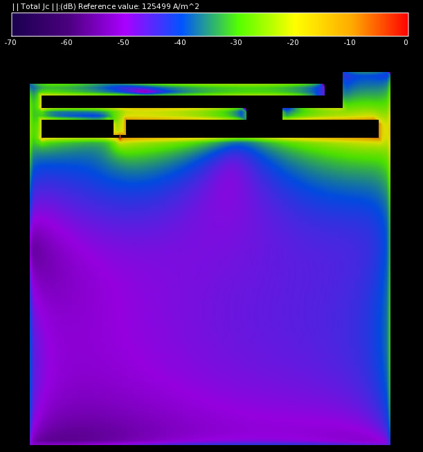
Figure 4: Surface currents on the antenna at 6.43 GHz.
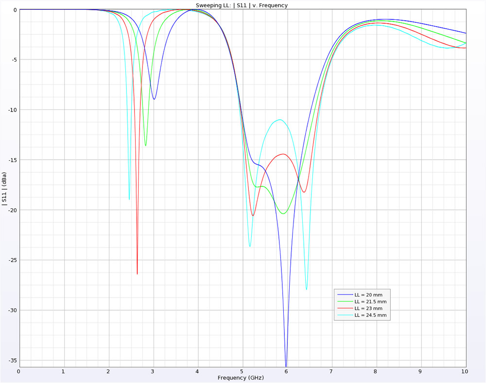
Figure 5: Return loss vs. LL
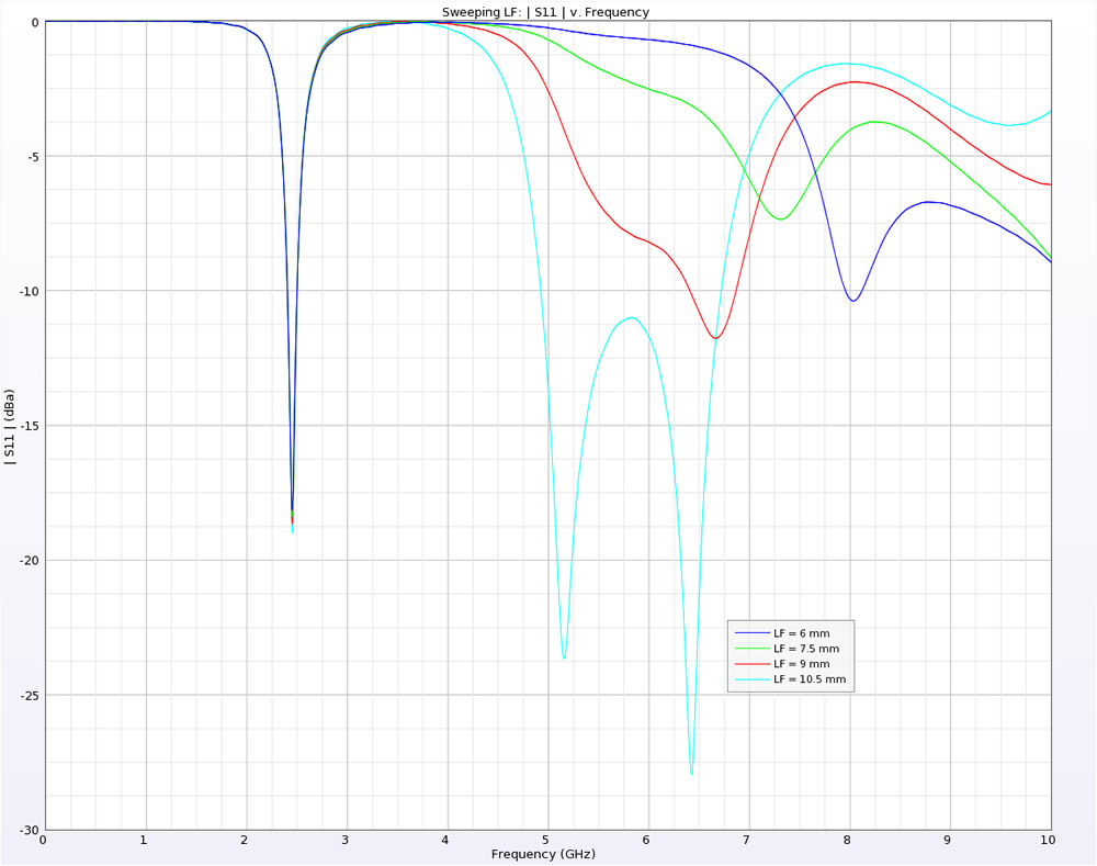
Figure 6: Return loss vs. LF
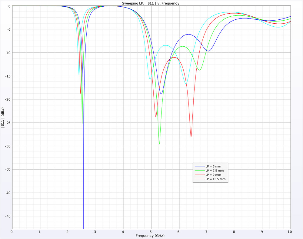
Figure 7: Return loss vs. LP
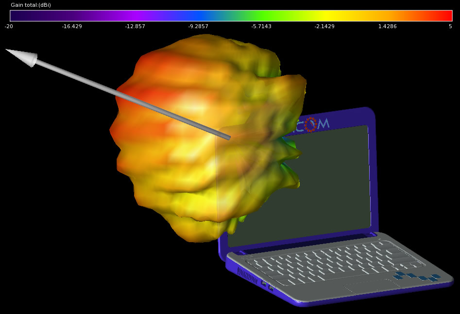
The antenna is now placed appropriately in the netbook. Figure 8 shows the antenna located in the upper corner of the computer lid with a cable attaching it to the motherboard. A combination of automatic fixed points and grid regions is employed to minimize memory usage. An initial simulation of the antenna is performed using the original free space parameters. It shows that the resonance near 2.4 GHz is unchanged; however, the upper frequency band is affected substantially. The earlier investigation of the antenna indicates that increasing the parameter LF will help correct this change. Figure 9 compares S11 of the antenna in free space, before tuning, and after increasing LF to 12 mm. The resulting 3D radiation pattern at 5.2 GHz is displayed with the main lobe direction in Figure 10.
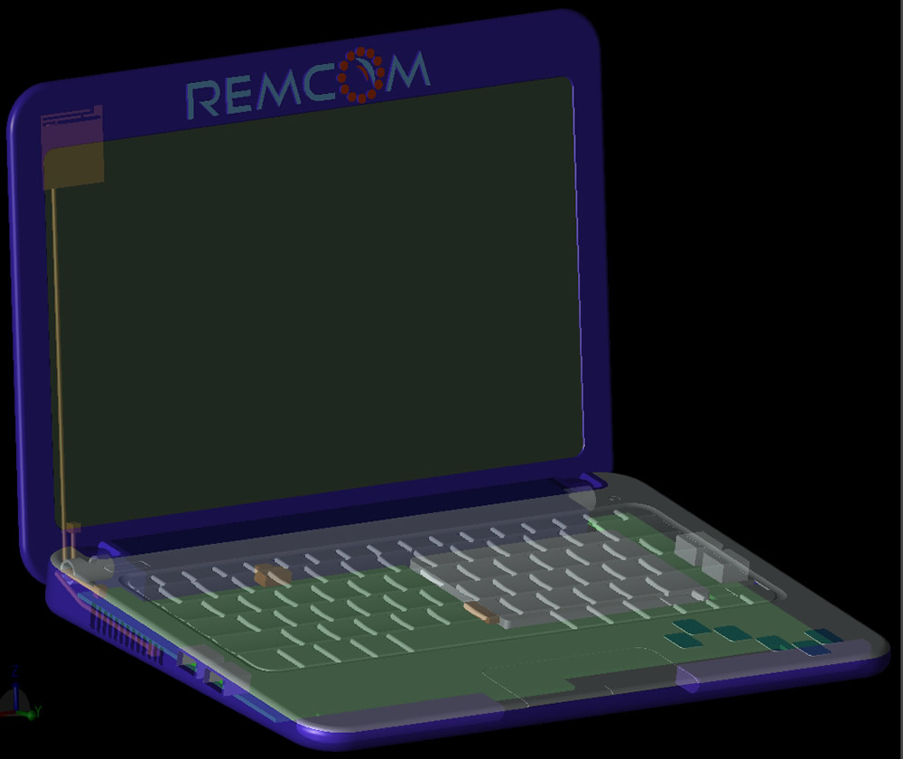
Figure 8: Antenna placement in netbook computer.
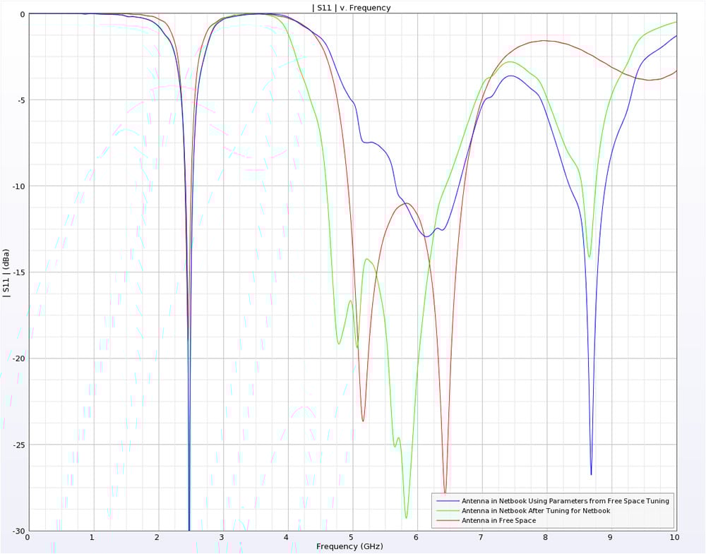
Figure 9: Comparison of antenna performance in free space vs. in the computer before and after tuning.