Introduction
Dielectric resonator antennas (DRAs) are a good choice for millimeter wave applications due to their low loss and high efficiency. Designing the resonator for a fundamental mode can be complex due to the small size and sensitivity of the resonator to fabrication errors. In this example, a larger cylindrical dielectric resonator is simulated in XFdtd to show how the excitation of the higher order modes HEM113 and HEM115 can be used to produce wide bandwidth and good gain performance. The design referenced in this antenna simulation comes from the conference paper cited below [1]. The results presented here are in good agreement with the simulated and measured results of the paper.
Device Design and Simulation
A cylindrical dielectric with relative permittivity of 7, height of 8.5 mm, and radius of 1.5 mm is used as the resonator in this design. The cylinder is mounted on a ground plane and fed by a coaxial probe that extends 1.9 mm above the surface of the ground plane and is in contact with the side of the cylinder as shown in the CAD representation of the geometry in Figure 1.
The return loss for the antenna is plotted in Figure 2, and it shows an operating band (S11 > -10 dB) from about 22 to 29 GHz. The steady-state electric field distribution is plotted in Figure 3 at 25 GHz and shows the HEM113 mode while Figure 4 at 28 GHz shows the HEM115 mode in the dielectric resonator.
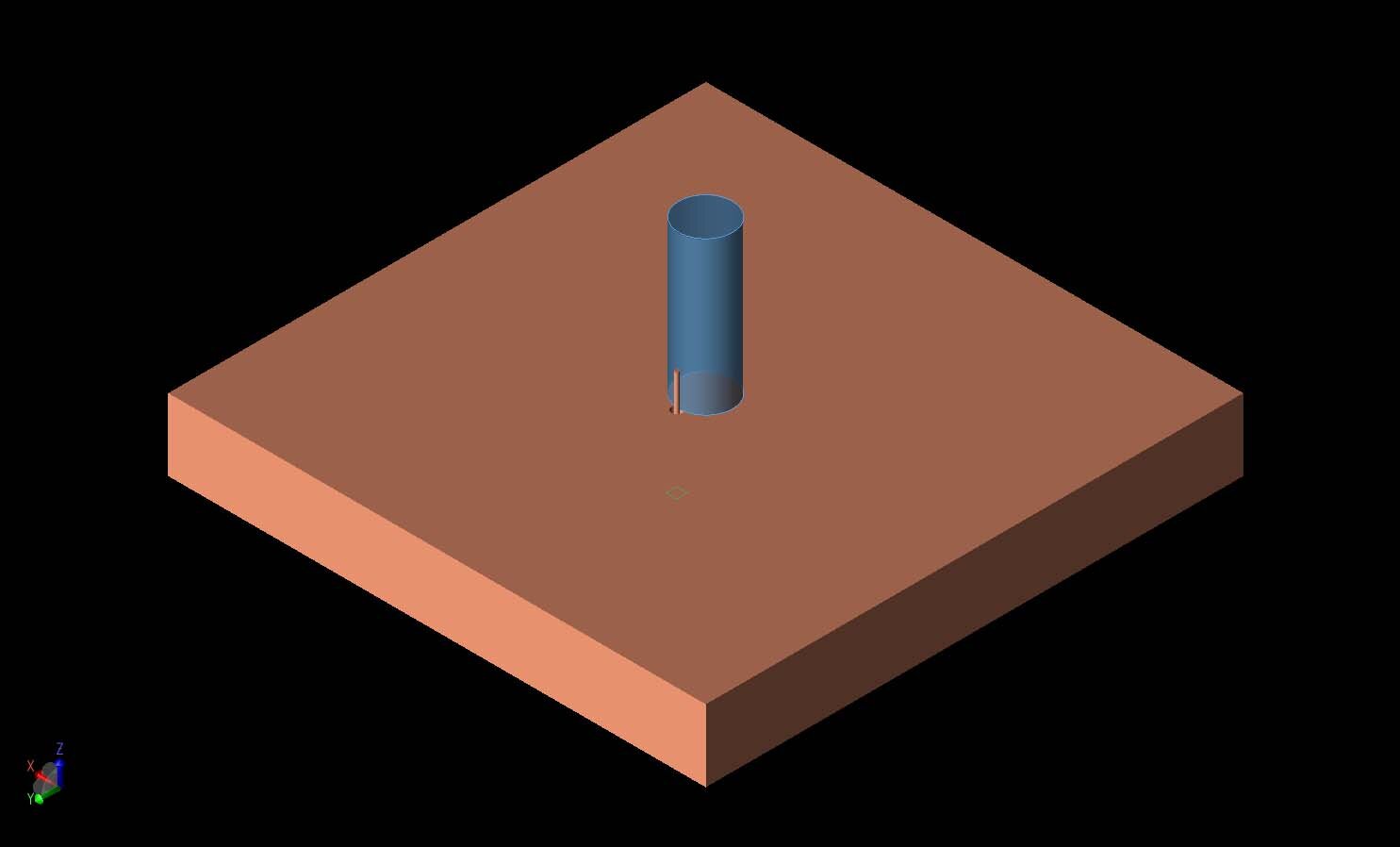
Figure 1: A three-dimensional CAD representation of the geometry is shown with a conducting ground plane under a cylindrical dielectric resonator with permittivity of 7. The resonator is excited by a coaxial probe on one side of the cylinder.
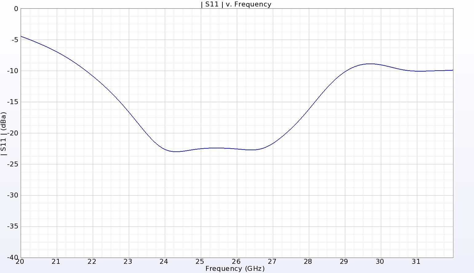
Figure 2: The return loss for the DRA has a broad bandwidth extending from 22 to 29 GHz.
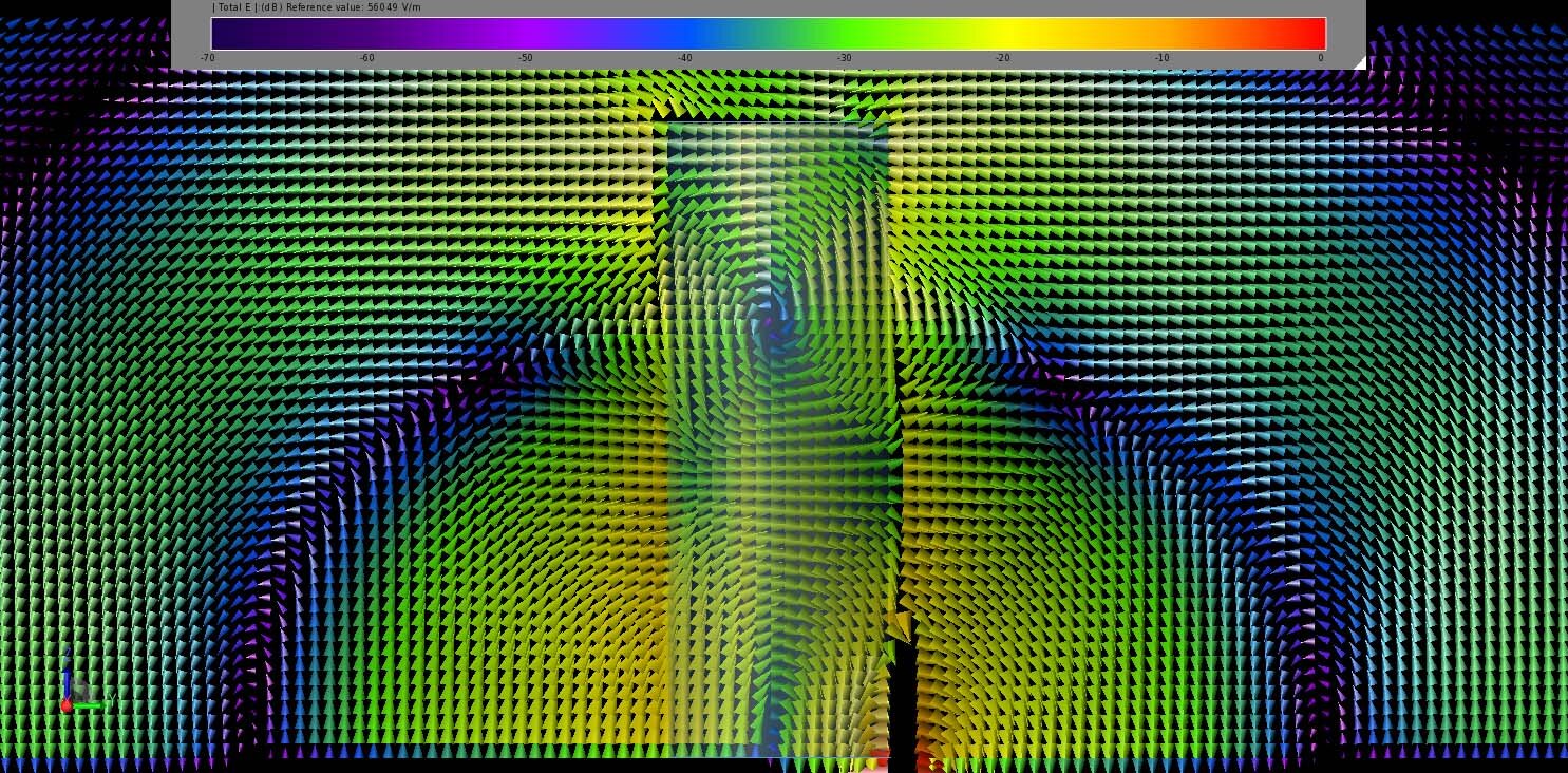
Figure 3: The steady state electric field distribution in and around the DRA at 25 GHz displays the lower HEM113 mode of the antenna.
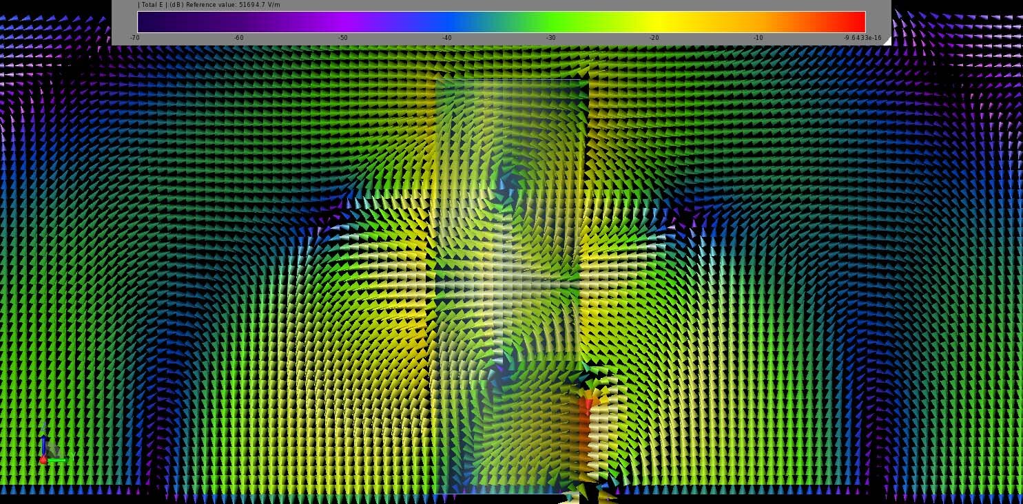
Figure 4: At 28 GHz, the steady state electric field distribution contains the HEM115 mode.
The far-field gain at a point directly above the cylinder, shown in Figure 5, varies from about 5.2 dBi at 22 GHz up to a peak of 8.8 dBi at 29 GHz, with a fairly smooth transition over the intermediate frequencies. The antenna has good efficiency as displayed in Figure 6, where the radiation efficiency is nearly 100% and the system efficiency, which includes the mismatch losses, ranges from 90 to 99% over the operating bandwidth.
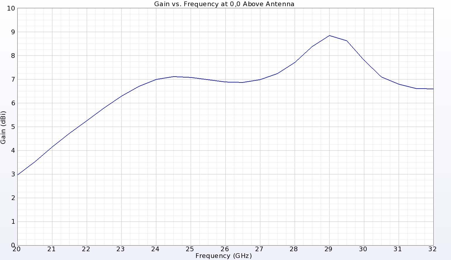
Figure 5: The gain directly above the DRA, which is also the peak gain direction, is fairly smooth and ranges from 5.2 dBi at the lower 22 GHz end to 8.8 dBi at the higher 29 GHz end of the band.
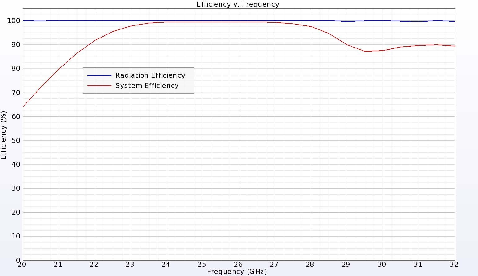
Figure 6: The DRA has excellent efficiency above 90% for the entire frequency range.
The three-dimensional antenna patterns at 25 GHz (Figure 7) and 28 GHz (Figure 8) show broad patterns with minimal lobing and the strongest gain of over 7 dBi directed above the cylinder in the Z direction. In the vertical XZ direction at 25 GHz, the gain is primarily from the phi component, as shown in Figure 9. In the YZ direction at 25 GHz, the theta component is dominant and any cross-polarized gain is down 50 dB from the co-polarized gain, as shown in Figure 10. Very similar results for both cuts of the pattern are found at 28 GHz and shown in Figure 11 and Figure 12. All these gain pattern results are close matches to the results measured by the authors of [1].
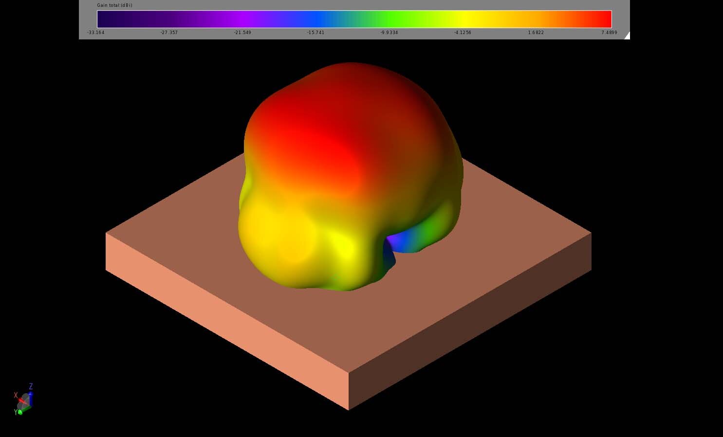
Figure 7: The three-dimensional far-field gain pattern for the antenna at 25 GHz is broad with minimal lobing and a 3dB beamwidth of about 68 degrees.
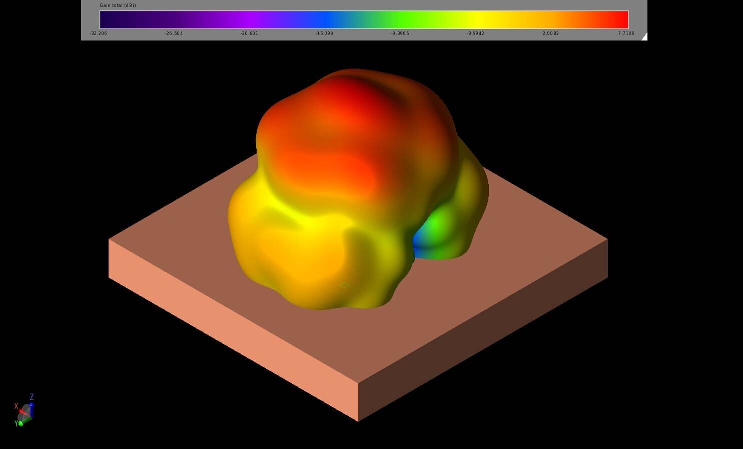
Figure 8: At 28 GHz, the three-dimensional far-field gain pattern is nearly identical to the pattern at 25 GHz with only slightly higher peak gain.
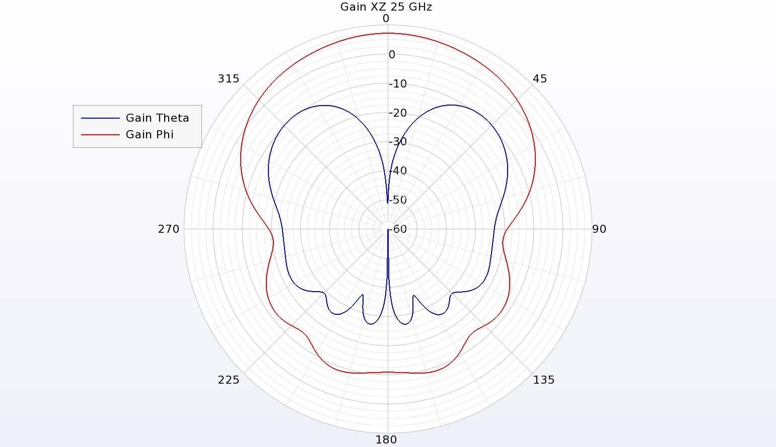
Figure 9: In the vertical XZ plane of the antenna at 25 GHz, the phi-directed gain dominates but the cross-polarized theta gain is down only about 10 dBi.
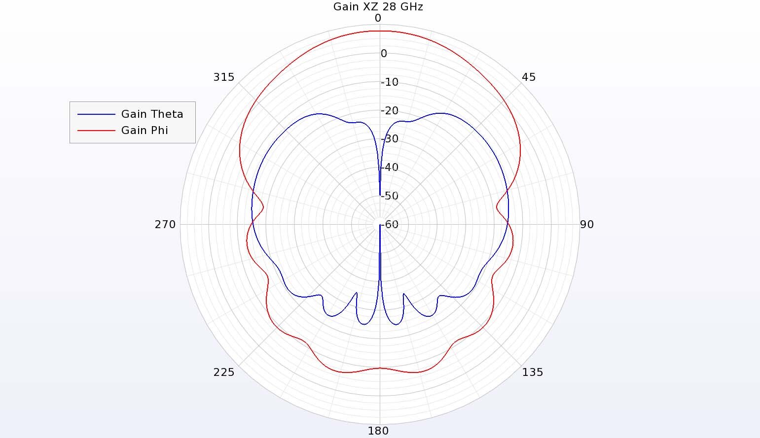
Figure 11: At 28 GHz, the gain in the XZ plane has a strong phi-directed pattern with a cross-polarized theta-directed pattern, similar to the pattern at 25 GHz.
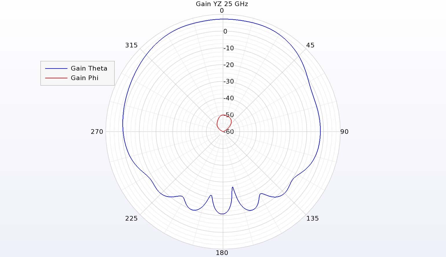
Figure 10: In the YZ plane, the theta gain is dominant with the cross-polarized gain down over 50 dB.
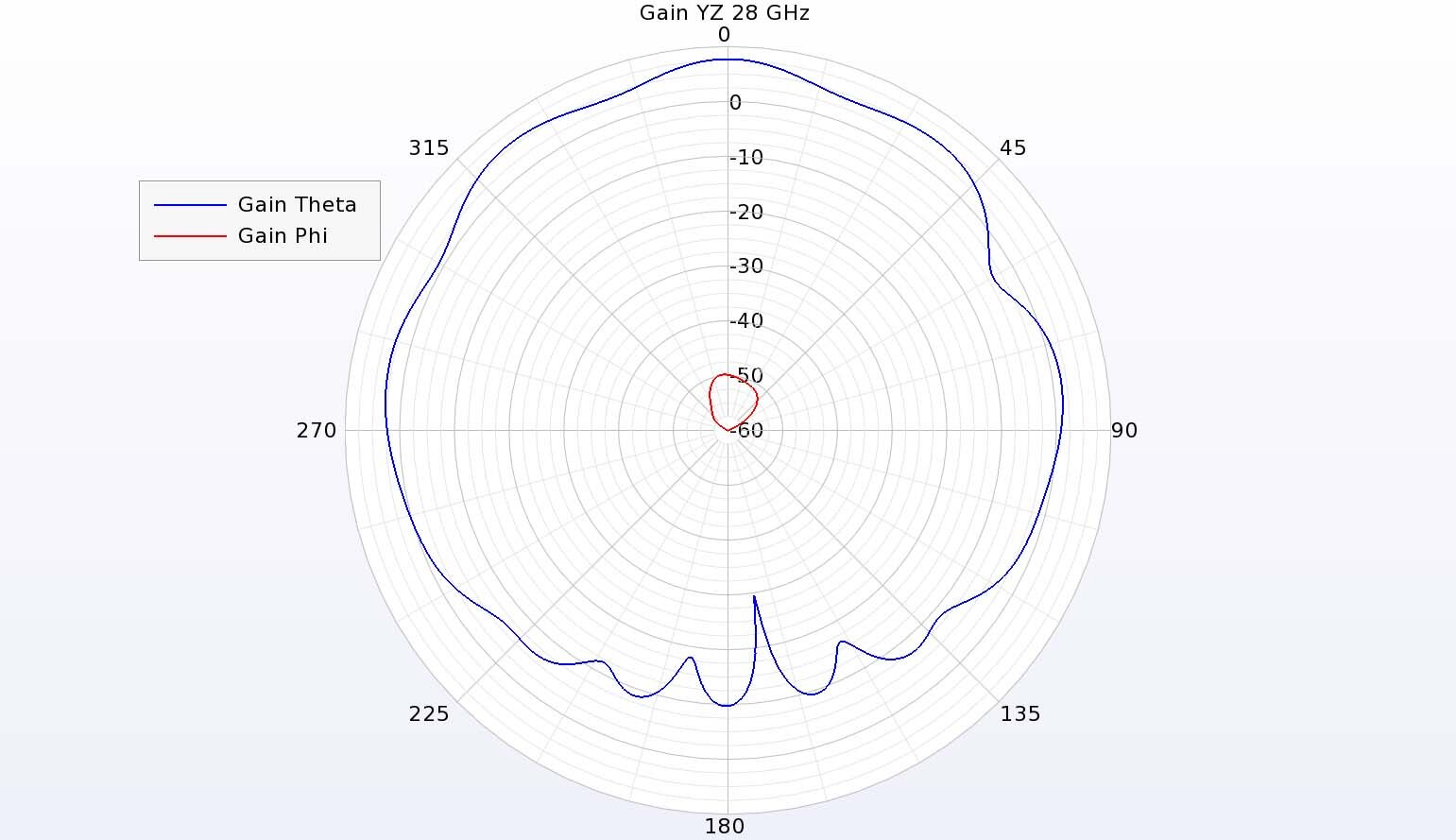
Figure 12: The theta-directed gain is dominant at 28 GHz in the YZ plane with minimal cross-polarized gain.
Conclusion
Dielectric resonator antennas can be good choices for millimeter wave applications, but there are practical issues with the fabrication of small components. Here, a larger dielectric resonator is simulated to reduce the susceptibility to dimensional errors by exciting higher order modes. The antenna has good performance over a wide bandwidth in the 22-29 GHz range.
Reference:
[1] L. Y. Feng and K. W. Leung, "Millimeter-wave wideband dielectric resonator antenna," 2015 40th International Conference on Infrared, Millimeter, and Terahertz waves (IRMMW-THz), Hong Kong, China, 2015, pp. 1-2, doi: 10.1109/IRMMW-THz.2015.7327734.


