By Apoorva Pedgaonkar and Gregory Moss, Remcom
Most electromagnetic (EM) simulations follow a familiar pattern: engineers enter a fixed set of material properties, geometries, and source conditions into a tool and receive a single, deterministic result. But design decisions, compliance determinations, and/or manufacturing tolerances based on a single deterministic simulation rely on the implicit assumption that real-world performance will mirror the model, which often proves untrue.
Uncertainty Quantification (UQ) mathematically estimates and measures the reliability of computational models and real-world predictions, turning a deterministic value into a realistic range of outcomes with associated degrees of confidence. In so doing, UQ provides depth of information vital to making risk-informed decisions, making it an increasingly valuable tool that offers multiple paths forward to improve the speed, precision, and real-world predictive accuracy of EM simulation. However, UQ is rarely available in commercial EM simulation software tools.
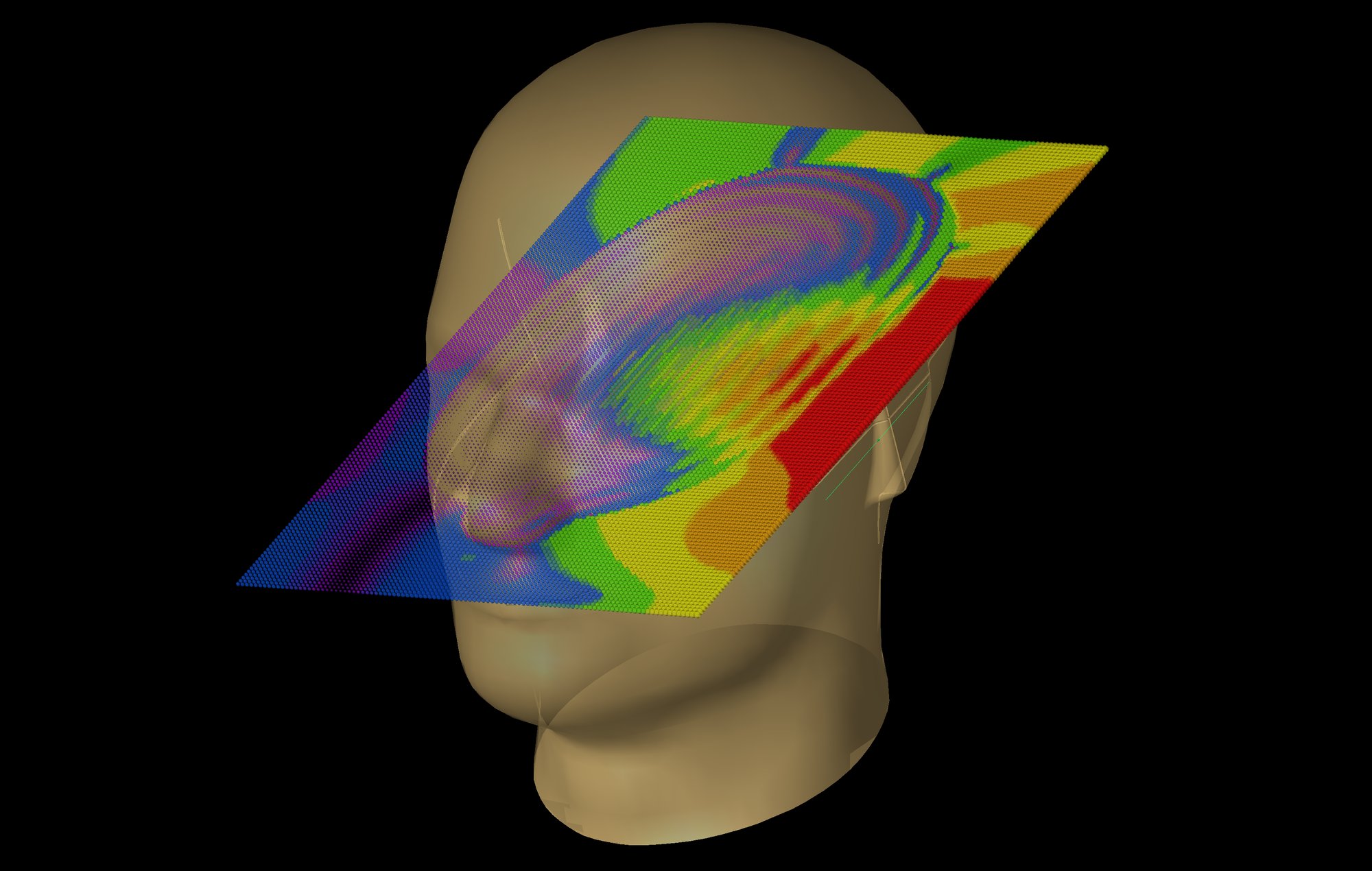 The image illustrates the overlaid field distribution, calculated by combining multiple deterministic fields. The smudged region within the head highlights how internal material uncertainties blur and affect the overall field path.
Why UQ Is Necessary And How It Works
The first step in UQ is determining whether a scenario requires it. A typical EM simulation can be useful anywhere a single, nominal-value result is needed to make a pass/fail or go/no-go decision, justify a design margin, quantify compliance or risk, or determine a manufacturing tolerance. However, in such cases, knowing the potential deviations around a nominal result is often more crucial than the nominal result itself. Further, the more data available about materials or components in advance of simulation, the more trust the user can gain regarding the simulation’s results.
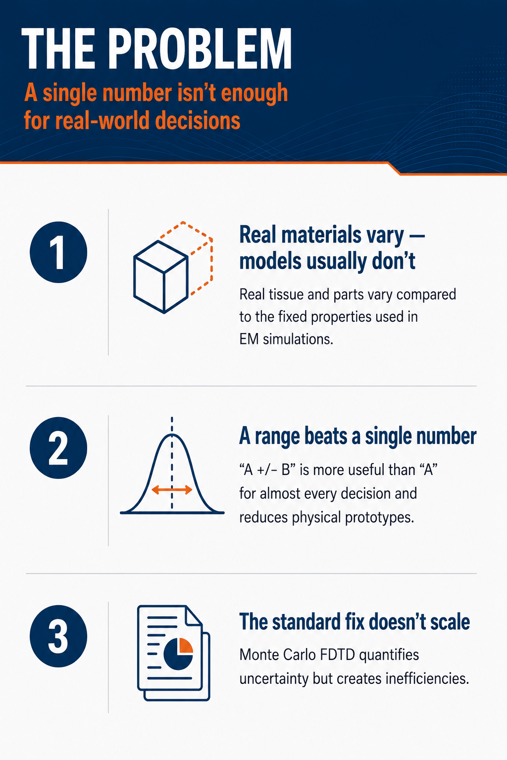
The key benefit of UQ is greater insight into various usage scenarios for the product being designed. With any EM simulation problem, a result of “the answer is A, +/- some deviation B” will always be more informative than “the answer is A.” The additional data and context can save engineers from having to build additional physical prototypes in response to unexpected test results, thereby streamlining the design process by providing more robust initial data.
A common misconception holds that UQ is solely materials-focused, since small changes in material properties can impact EM simulation results (material uncertainty). However, there are other types of uncertainties which can impact EM simulations. One is geometric uncertainty, where the shape and size of the simulation object can lead to variations in the EM simulation results. Another is component-level uncertainty, as specified in the respective data sheets for different circuit components (like resistors, capacitors, and inductors, etc.). These uncertainties are commonly referred to as manufacturing tolerances. Identifying which uncertainty to focus on depends entirely on the application.
An example of material uncertainty is depicted in Figure 1, which shows a SAM head phantom excited by a 2 GHz dipole antenna using XFdtd®, Remcom’s 3D EM simulation software, positioned next to the ear. Figure 1 shows three deterministic EM simulations on the SAM head phantom, where perturbing the dielectric constants and conductivities results in observable shifts in the internal electric field distribution. Figure 2 depicts an XFdtd electric mesh of the SAM head with the antenna positioned next to it.
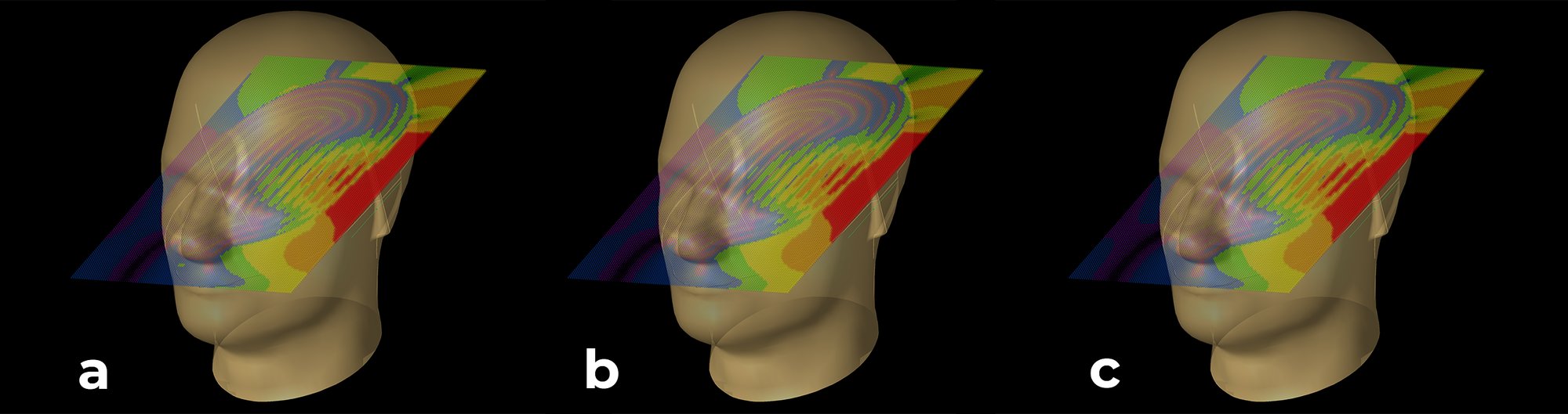 Fig 1: Electric field distribution from an EM deterministic simulation on a 3D scanning acoustic microscopy (SAM) head phantom exposed to a 2 GHz dipole antenna, featuring varying material properties: (a) Baseline tissue-equivalent properties (inner head εr = 44.3, inner head σ=1.58 ( S/m), outer head εr =2.89); (b) Modified tissue-equivalent properties (inner head εr = 39.7, inner head σ=1.43 ( S/m), outer head εr =2.64); and (c) Another modified tissue-equivalent properties (inner head εr = 36.1, inner head σ=1.30 ( S/m), outer head εr =2.43). All simulations use an identical input power and identical antenna positioning.
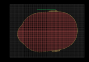 Fig. 2: A 2D mesh ZY slice of the 3D SAM head phantom showing the two layers of the 3D SAM head phantom. The outer layer is a lossless dielectric and the inner layer is a lossy dielectric.
Available UQ Techniques
A variety of approaches have been established to incorporate uncertainty into EM simulation. Primarily, the UQ techniques are classified into two categories: intrusive and non-intrusive methods. Non-intrusive methods leave the original computational formulation completely untouched, running it multiple times with different sampled input parameters to map the output. For example, Monte Carlo analysis, which translates fixed-value inputs into probability distributions (e.g., normal, uniform, log-normal), is considered a non-intrusive method. All variations are run individually, and then the results are combined. Because Monte Carlo simulations can range from a few simulations to thousands, execution time increases with the number of simulations. It is generally not a feasible solution for larger problems, including understanding a signal's impact on the human body, simulating a complex circuit, or investigating a circuit prone to regular changes.
More specialized intrusive methods modify the underlying computational algorithms to embed uncertainty formulations directly into the governing equations. These are designed to provide similar statistical insight more efficiently. They include polynomial chaos expansion (PCE) and Stochastic Finite-Difference Time-Domain (S-FDTD). PCE approximates a complex computational model as a series of orthogonal polynomials, effectively transforming stochastic (random) problems into deterministic ones. S-FDTD, meanwhile, calculates EM wave behavior when interacting with materials that feature random or uncertain properties, such as varying conductivity or permittivity, or materials with geometrical variation. It computes the mean and variance of the EM field in a single simulation.
Both Intrusive PCE and S-FDTD are single simulations, whereas Monte Carlo uses multiple simulations. But PCE and S-FDTD require additional computational complexity, which has inhibited their accessibility to most engineers. Currently, these methods require specialized statistical tools or research-level effort to integrate into a day-to-day engineering workflow, but researchers are rapidly advancing toward making each method more efficient and practical enough to integrate seamlessly into routine engineering workflows.
Real-World Use Cases
UQ typically begins by gathering available design statistics and running a Monte Carlo-based simulation, randomizing the material property of least confidence, and examining the resulting mean and standard deviation. In practice, hundreds or often thousands of simulation runs may be required for reliable statistics, but for a small model, that remains a reasonable, overnight job.
Running manageable Monte Carlo simulations is an effective way for engineers to gain firsthand experience in reading and understanding a distribution of outcomes, rather than a single number. However, because Monte Carlo is not suited to large-scale problems, it should not be the default first step, but rather, the appropriate starting point when a scenario justifies its use.
A real-world example of this approach is the analysis of a material used to simulate tissue properties in the human body, which vary between tissue types and individuals. The results of such an analysis could be applied to design tolerances for how much power from the radiating antenna of a cell phone or a Bluetooth-enabled watch can safely be absorbed by human tissue, a metric called specific absorption rate (SAR). If that rate varies, the established signal radiation standard might not hold true in all scenarios, and that variability must be accounted for in device design.
Applying the material uncertainty to the simulation shown in Figure 1 allows SAR uncertainty to be quantified. Since it is unknown how much the material inside the SAM head can vary, IEC/IEEE 62209-1528 uncertainty correction is applied in this example. According to this, a +/- 10% deviation in the material properties of the SAM head phantom can introduce up to a 2% change in the average 1g (SAR) values.
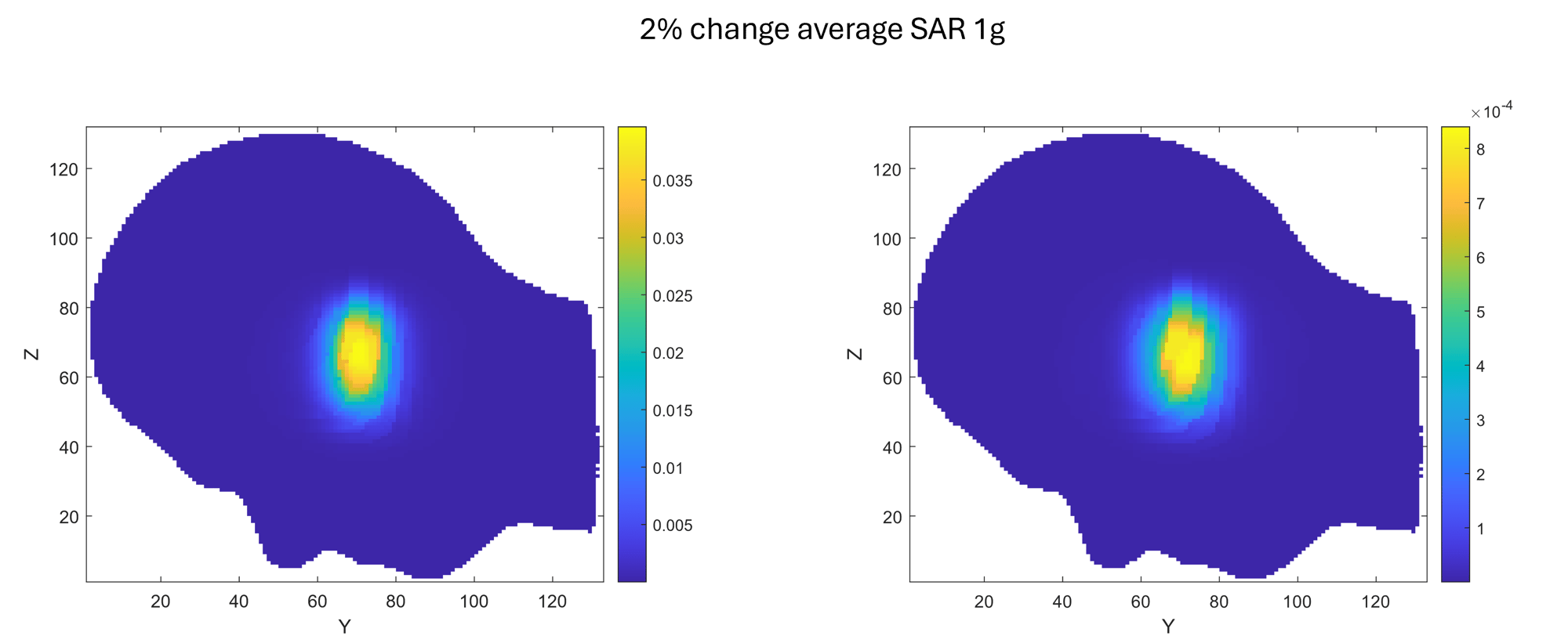 Fig. 3: Average SAR 1g results. (L) depicts a 2D slice of mean SAR due to material variation. (R) shows a 2D slice of the standard deviation of the SAR due to material variation. (Note the color bar scale is different.)
The mean image (Figure 3 above) has a max mean value of 0.0396 W/kg, and the deviation image has a max deviation value of 8.4e-4 W/kg. This corresponds to a 0.0396 +/- 8.4e-4 (W/kg) average 1g SAR. This can also be expressed as a ~1.9% change in the average 1g SAR value. This comes very close to the uncertainty correction described in the IEC/IEEE 62209-1528 standard.
UQ As A Daily Use Tool
UQ has historically relied on academic codes or custom scripts that require specialized statistical knowledge to set up. This approach is adequate for a research paper, but it means most practicing engineers lack the opportunity to apply UQ, even when their problem would benefit from it.
Monte Carlo analysis can be performed using XFdtd, which turns a separate research exercise into a normal step in engineers’ existing workflow. In practice, engineers can calibrate their model the same way they always do, starting with the geometry, materials, sources, and boundaries; UQ is essentially an additional workflow rather than a different modeling environment. Engineers do not need to learn a new modeling paradigm; they need only add a description of how a property varies in lieu of its nominal value and follow the workflow. In short, the biggest shift is mental, not technical: users must build their confidence interpreting a mean-and-deviation result instead of a single number.
Further, Remcom is working to implement more advanced computational methods in XFdtd that will be appropriate for simulating and solving larger, more complex problems. Future upgrades will empower design engineers to use different UQ approaches, choosing the one most appropriate to the size and nature of their problem. Material property uncertainty is the starting point for this effort, but there are also plans to support geometric and circuit component uncertainty. Additionally, XFdtd supports XStream® GPU Acceleration for ultra-fast FDTD computations. Using latest-generation GPUs, XStream enables XFdtd calculations to complete in minutes, compared to hours or even days on a CPU alone. Advanced computational methods for UQ will be seamlessly integrated with the current GPU execution.
Conclusion
In summary, engineers need software to build confidence that designs will hold up in real-world conditions. Enhancing simulation options enables faster iteration, reduced reliance on costly physical prototypes, and cleaner initial designs brought into integration, and Remcom is at the forefront of building that capability.
About The Authors
Apoorva Pedgaonkar is an Electromagnetic Research Engineer for Remcom, working as part of the XFdtd Research Team. She holds a Ph.D. in Electrical Engineering (Computational Electromagnetics) from the University of Utah, where her research focused on uncertainty analysis in FDTD and on FDTD modeling of power-line radiation through the magnetized ionosphere. Her industry experience spans multiple fields, including uncertainty quantification, signal and power integrity, and systems engineering for MRI technology.
Gregory Moss is the XFdtd Research Manager for Remcom and has over 20 years of experience in the computational electromagnetics (CEM) industry. He has a comprehensive understanding of the past and present of the full-wave CEM market, including the strengths and weaknesses of current commercial and open source software packages based on the Finite-Difference Time-Domain (FDTD), Finite Integration Technique (FIT), Discontinuous Galerkin Time Domain (DGTD), Finite Element Method (FEM), and Method of Moments (MoM), among others. He also has substantial experience developing computational solvers for circuit, electrostatic, and kinetic particle and plasma simulations.
About Remcom
For more than 30 years, Remcom has provided electromagnetic simulation and wireless propagation software for commercial organizations, government agencies, and research institutions. Our innovative software and engineering expertise help design teams reduce development time, improve product performance, and solve complex electromagnetic challenges across applications including antenna design, wireless communications, automotive radar, aerospace, and defense. Flexible licensing options, responsive technical support, and custom-engineered solutions enable organizations of all sizes to accelerate product development with confidence.
Resources
- Electromagnetic Uncertainty Analysis of 3D Biological Phantoms | IEEE Conference Publication | IEEE Xplore.
- A Stochastic Scattered-Field FDTD Formulation Using a Highly Efficient FDTD Discrete Plane Wave Source for Weak Scattering Environments | IEEE Journals & Magazine | IEEE Xplore.
- S. M. Smith and C. Furse, "Stochastic FDTD for Analysis of Statistical Variation in Electromagnetic Fields," in IEEE Transactions on Antennas and Propagation, vol. 60, no. 7, pp. 3343-3350, July 2012, doi: 10.1109/TAP.2012.2196962.
- K. Masumnia-Bisheh, K. Forooraghi, M. Ghaffari-Miab and C. M. Furse, "Geometrically Stochastic FDTD Method for Uncertainty Quantification of EM Fields and SAR in Biological Tissues," in IEEE Transactions on Antennas and Propagation, vol. 67, no. 12, pp. 7466-7475, Dec. 2019, doi: 10.1109/TAP.2019.2930171.
- Analysis of Electromagnetic Wave Propagation in Variable Magnetized Plasma via Polynomial Chaos Expansion.