Configurable Array Antenna Simulation for Base Stations
A MIMO antenna design available in the literature [1] is created and simulated in XFdtd to generate Return Loss, Coupling, and Gain Patterns for several different configurations and operating modes of the device. The antenna is intended to operate between 1.7 - 2.2 GHz, to simultaneously operate with both horizontal and vertical polarized patterns, and to allow beamforming or omni-directional patterns. The intended use of this antenna is for base stations.
The overall antenna design is shown in Figure 1 and is comprised of three portions: a center disk of four magnetic dipoles which produce a horizontally polarized pattern, and top and bottom ground planes which each have four electric monopoles for vertically polarized patterns. The center disk of magnetic dipoles is shown in Figure 2 and the lower array of electric monopoles is shown in Figure 3. An upper array of electric monopoles is the mirror image of the lower one and is phased 180 degrees apart from the lower array to ensure constructive addition of the patterns. The overall dimensions of the entire device are approximately 170x170x150 mm.
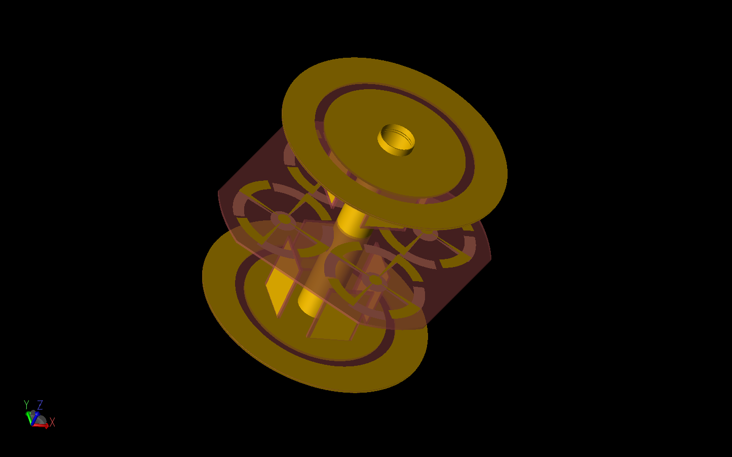
Figure 1: Shown is a three-dimensional CAD representation of the antenna array with electric monopole arrays above circular ground planes at the top and bottom of the device and a flat, four-element, magnetic dipole array at the center. The gold material represents copper while the red material is FR-4.
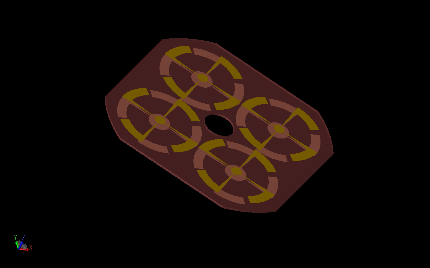
Figure 2: A detailed view of the center magnetic dipole array is shown. The four elements are printed on the top and bottom of the substrate material and are fed at the centers.
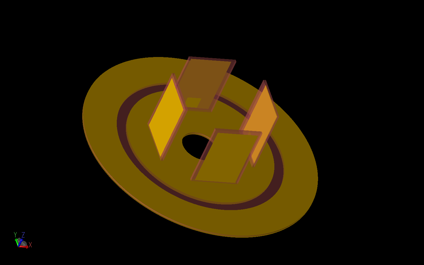
Figure 3: The lower electric monopole array is shown with the four elements arranged on the circular ground plane. There is a small feed patch on the inner side of each element.
The antenna is simulated with one port active at a time to generate return loss plots. The return loss for the electric monopoles can be seen in Figure 4 to be below -10 dB from approximately 1.7 to 2.2 GHz. Similarly, the return loss for the magnetic dipoles is shown in Figure 5 with good performance over the frequency range of interest. The coupling between elements in the electric dipole arrays (Figure 6) is highest, but still below -10 dB, between elements adjacent to the fed element and below -20 dB for the mirrored elements on the opposite side of the device. The coupling of the magnetic dipoles (Figure 7) is below -10 dB for all elements with and below -20 dB for the diagonally opposite antennas.
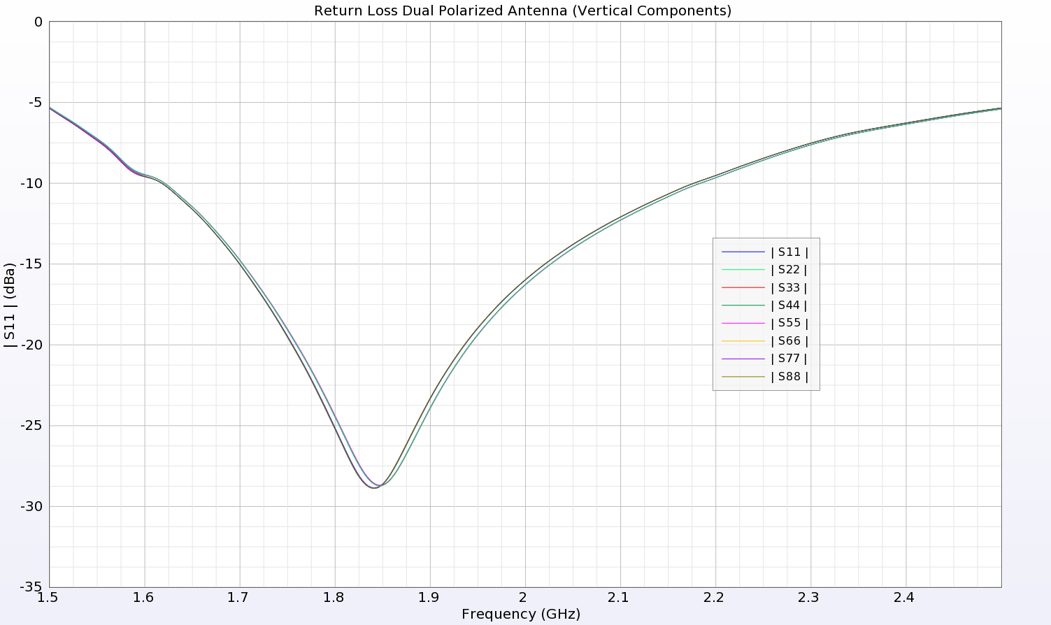
Figure 4: The return loss for each of the electric monopoles shows good performance over the 1.7-2.2 GHz band.
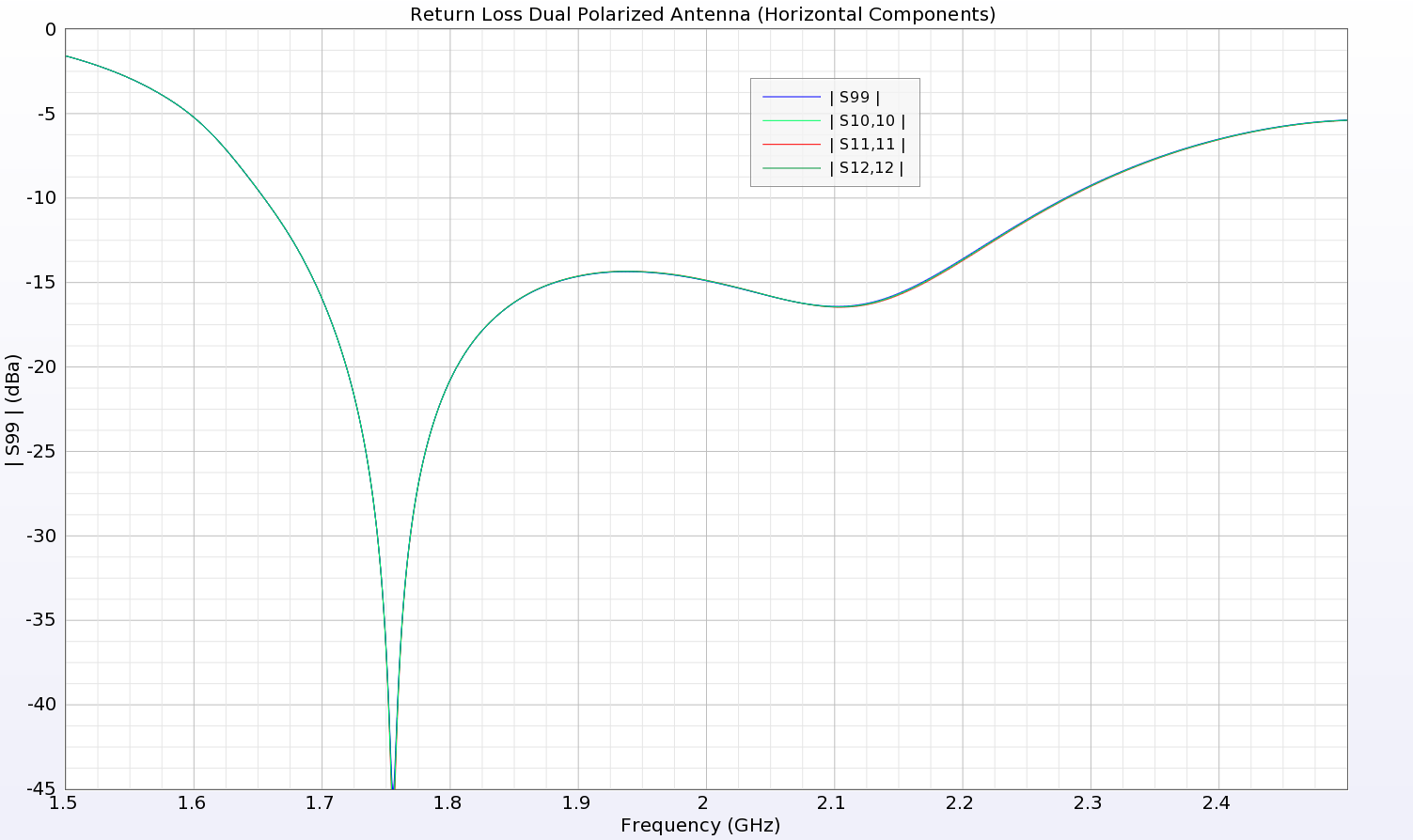
Figure 5: The return loss for the magnetic dipoles shows good performance over the 1.7-2.2 GHz band.
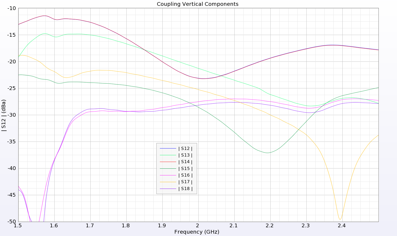
Figure 6: The coupling between elements of the electric monopole arrays remains below -10 dB for all elements with the highest coupling between elements adjacent to the feed and much lower coupling to the elements on the opposite end of the device, as expected.
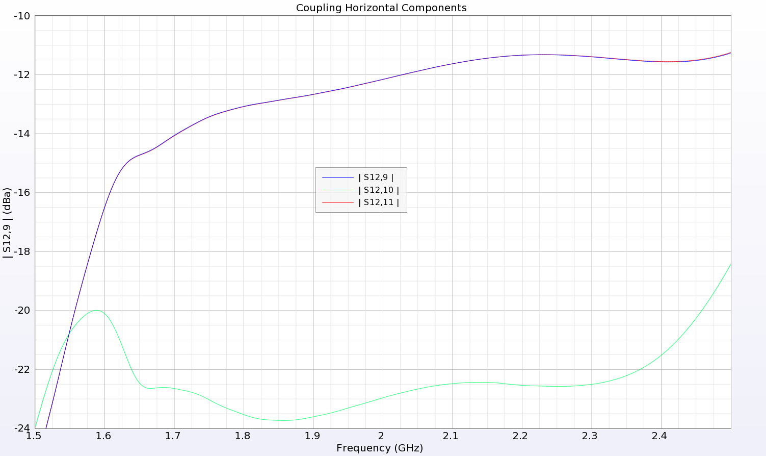
Figure 7: Coupling between the elements of the magnetic dipole array is below -10 dB and much lower for the diagonally opposite element.
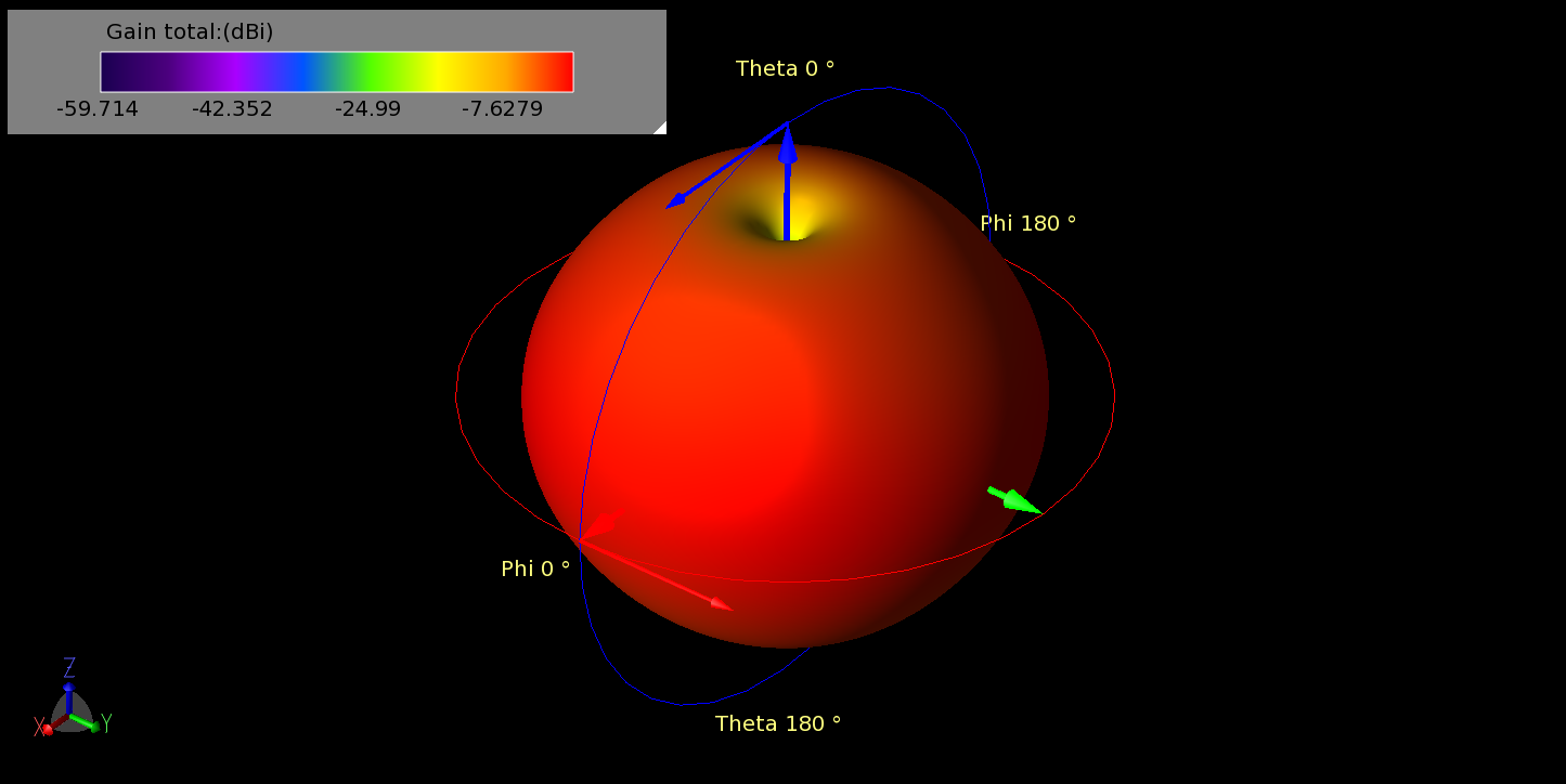
Figure 8: The three dimensional pattern of the horizontal array (magnetic dipoles) shows a uniform pattern in OMNI mode. The image is at 1.7 GHz but other frequencies are similar.
The device is capable of operating in numerous modes depending on the phasing of the elements and can produce horizontally and vertically polarized patterns from the separate arrays. When all elements are fed in phase, the pattern produced is omni-directional such as that shown in Figure 8 for the horizontally polarized pattern generated by the center magnetic dipole array at 1.7 GHz. A two-dimensional plot of the pattern through the center of the device is shown in Figure 9 where it can be seen that there is good uniformity of the pattern. Similarly, the vertically polarized patterns from the electric monopole elements in omni-directional mode at 1.7 GHz are shown in three dimensions in Figure 10 and in a two-dimensional plot in Figure 11. With both arrays active at the same time, both horizontal and vertical polarizations are produced as shown in Figure 12 for an azimuthal cut at 1.7 GHz.
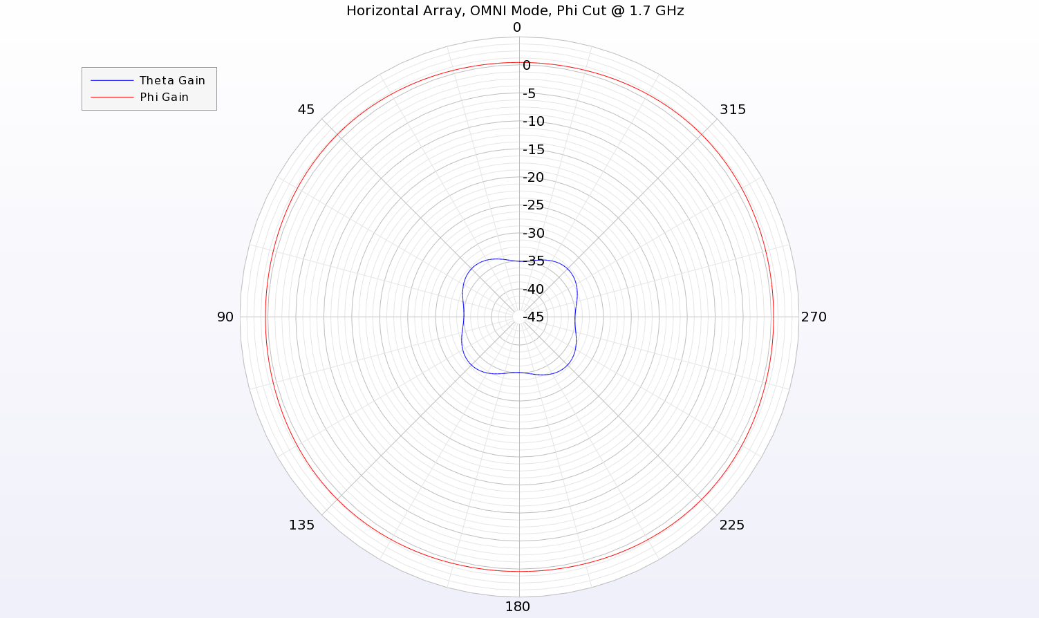
Figure 9: In the azimuthal plane around the device, the horizontal polarization (Phi) is quite uniform for the case of the magnetic dipole array in OMNI mode.
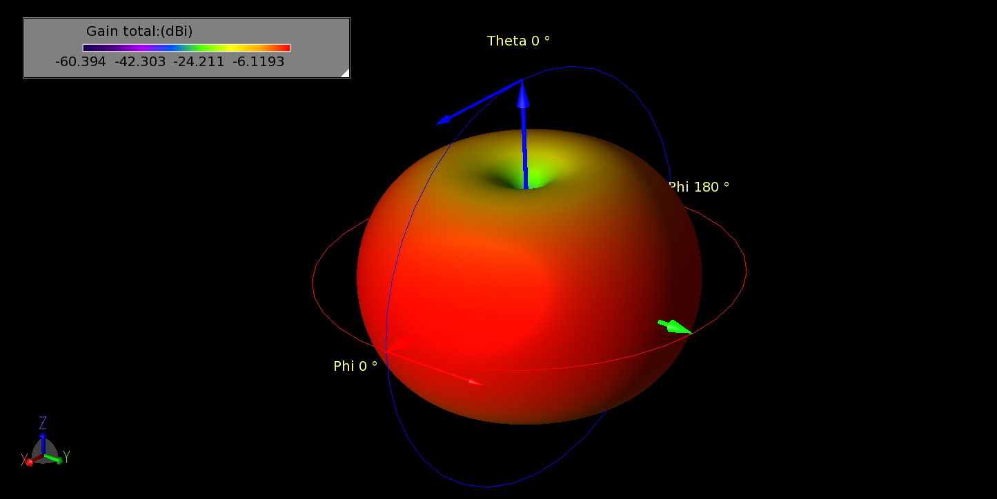
Figure 10: The vertical electric monopole arrays produce a uniform pattern in OMNI mode as expected. Shown in the pattern at 1.7 GHz.
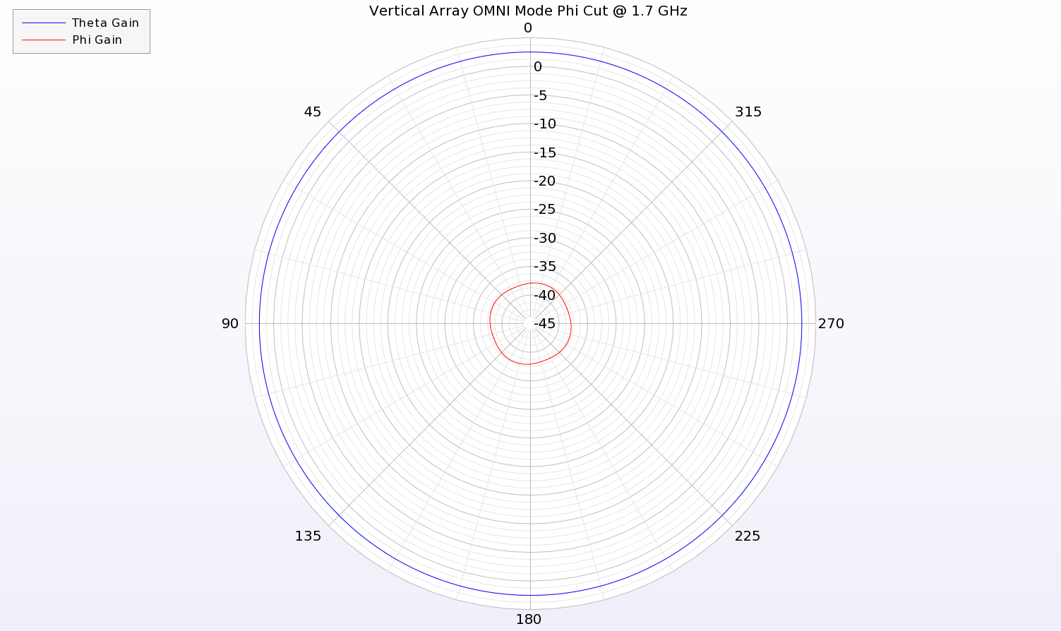
Figure 11: An azimuthal cut of the pattern at 1.7 GHz shows uniform gain of the vertical polarization (Theta) for the electric monopole array in OMNI mode.
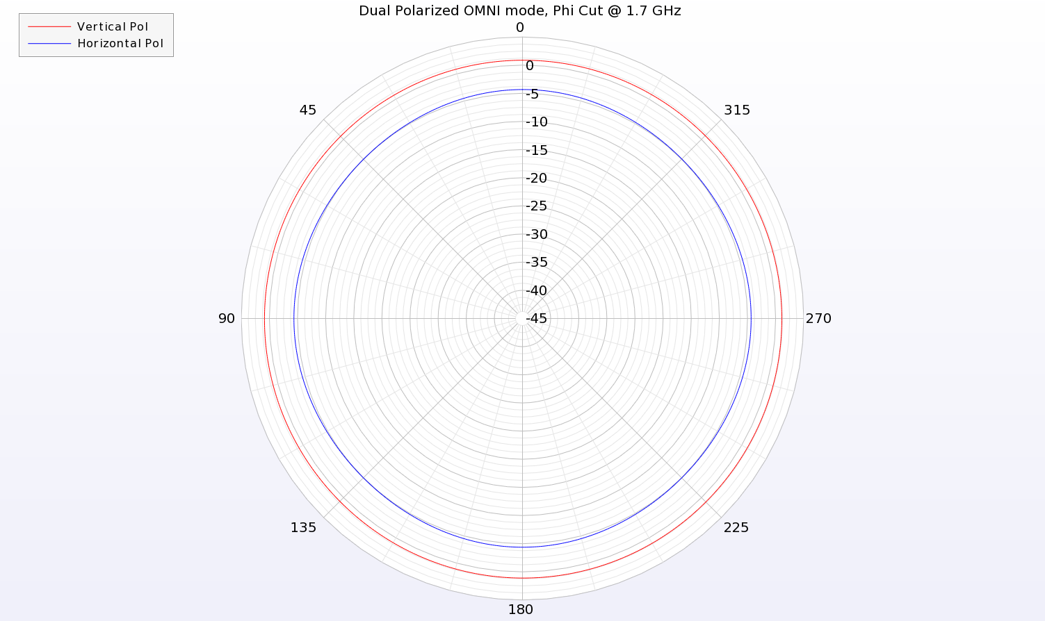
Figure 12: In dual polarization OMNI mode, both sets of arrays are fed and both horizontal and vertical polarizations are produced. The image shows an azimuthal cut through the pattern at 1.7 GHz and both the vertical and horizontal patterns are seen to be uniform.
To generate beams in a given direction, called Sector Mode, the phasing between the antenna elements must be adjusted. With a phasing scenario of [0, 90, 180, 90] applied to the feeds of each array (180 degree offset between top and bottom electric monopole arrays), the sector pattern will focus a beam to one side. A three-dimensional view of the generated pattern is shown in Figure 13 for the Sector Mode pattern at 2 GHz while a two-dimensional azimuth cut is shown in Figure 14.
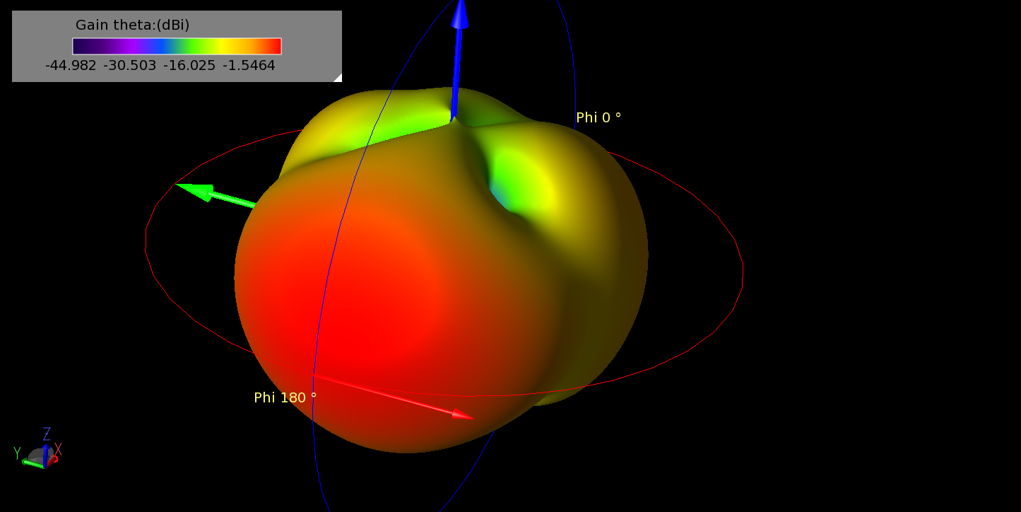
Figure 13: When operating in SECTOR mode, the antenna feeds are phased to produce a beam in a certain direction. In the image, a beam is shown pointing in the -X direction for the array at 2 GHz.
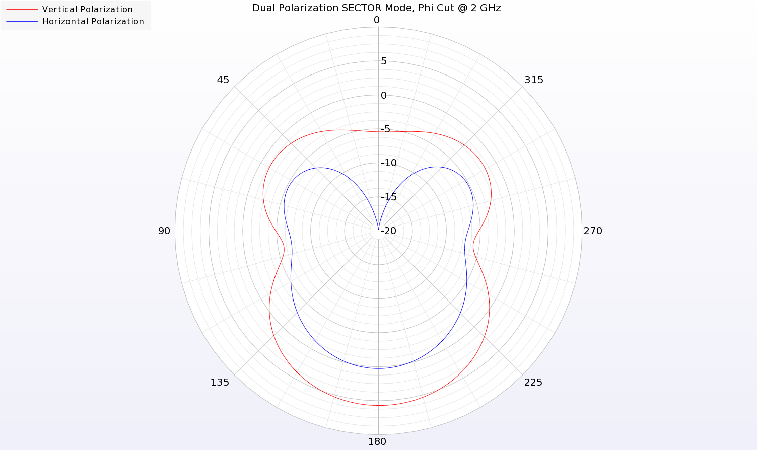
Figure 14: The two-dimensional azimuthal cut of the SECTOR pattern for the dual polarized antenna is shown at 2 GHz.
As the results show, the antenna array provides good performance over a broad frequency range and can produce both horizontally and vertically polarized patterns simultaneously. The ability to form either omni-directional or focused beams is also demonstrated making this design suitable for base station applications.
Reference:
[1] K. Prionidis, "MIMO configurable array for sector/omni-directional coverage," Department of Signals & Systems, Chalmers University of Technology, Gothenburg, Sweden 2014.
Request Project Files
Thank you for your interest in this application example. Please complete the form below to download the Configurable Array Antenna Simulation for Base Stations project files.


