Design of a Mobile Base Station Using Antenna Synthesis
This example uses a macro script from XFdtd's XTend library to design a mobile base station using an array of half wavelength dipoles. The procedure could be the first step in designing a new base station, or the technique might be used to match a commercially-available product and the resulting far-zone pattern used for cell site analysis within Remcom's Wireless Insite. As with other design-oriented offerings in XTend, this script does more than simply automate the design process for the array. It sets up the entire project -- materials, waveforms, feeds, grid, sensors, and even parameters. A user can be ready to run their simulation in just a few seconds.
After installing XTend, the Mobile Base Station Designer is available on XF's integrated Macros menu along with a number of other helpful extensions to XF as seen in Figure 1. Launching the script presents the user with the customized GUI in Figure 2 which allows the user to specify appropriate design criteria. Portions of the interface update dynamically as the user makes changes in order to offer suggestions on how many elements to use, warn if sidelobe suppression goals conflict with steering goals, and provide feedback on the resulting design.
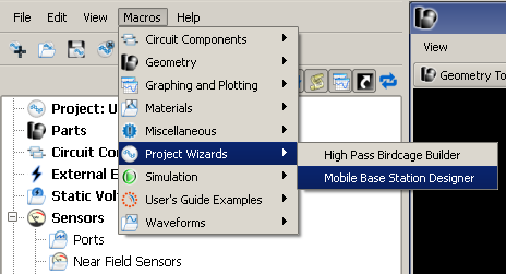
Figure 1: Menu entry to launch the mobile base station designer.
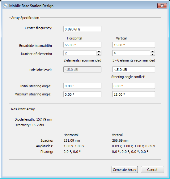
Figure 2: User interface of the base station designer.
The specifications for a commercially available base station antenna were used for this demonstration:
-
Center frequency: 893 MHz
-
Horizontal beamwidth: 65 degrees
-
Vertical beamwidth: 15 degrees
-
Beam tilt: 0 degrees
-
Sidelobe suppression: 15 dB
Although this product is not electrically steerable, the example assumes the new array will be. The dialog warns that the number of elements is insufficient to achieve the maximum electrical downtilt and simultaneously meet the sidelobe suppression goals. The warning is ignored for this purpose. Pressing OK prompts the script to generate the project.
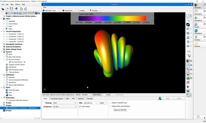
The script employs the Fourier transform technique to generate the array and a modified Taylor distribution to control sidelobes. The resulting antenna geometry with its feeds and materials can be seen in Figure 3. A number of parameters are generated to allow the user to control the dipole lengths, electrical downtilt, scan angle, component amplitudes and component phasing. Far-zone sensors are automatically added to capture the horizontal and vertical patterns in addition to the full 3D pattern. The script even prompts the user for a project name and location, so they can be ready to run their simulation immediately. This project requires approximately 150 MB of RAM, and each downtilt angle can be completed in about 45 - 60 seconds on four CPUs or six to seven seconds using XStream on a single C2070.
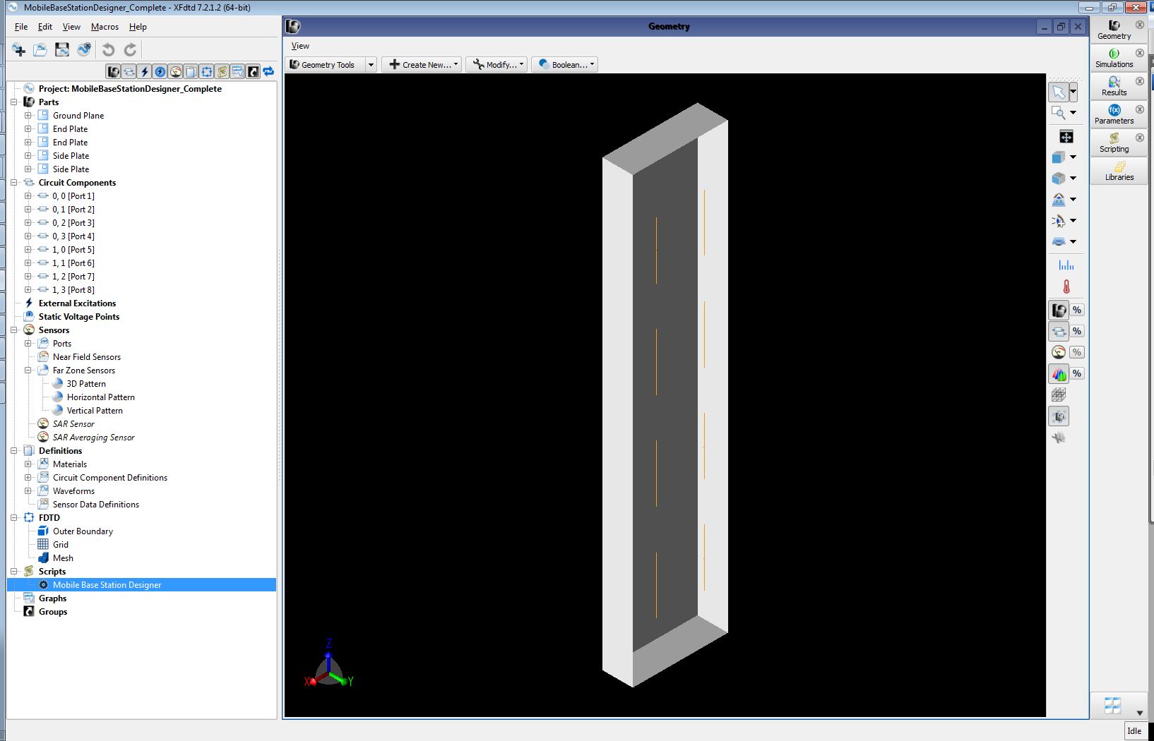
Figure 3: Completed base station geometry.
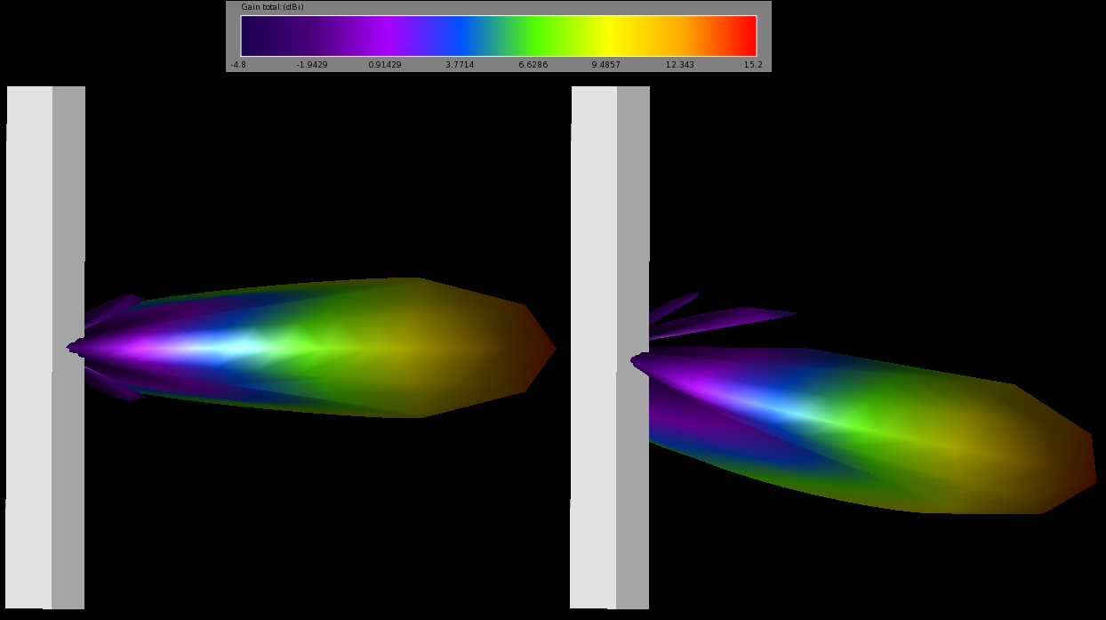
Figures 4 and 5 contain the horizontal and vertical patterns calculated by XFdtd. Steering of the pattern is demonstrated through a sweep of the automatically-parameterized electrical downtilt. The vertical patterns for several angles is shown in Figure 6. The full 3D patterns for 0 and 15 degree tilts is displayed in Figure 7.
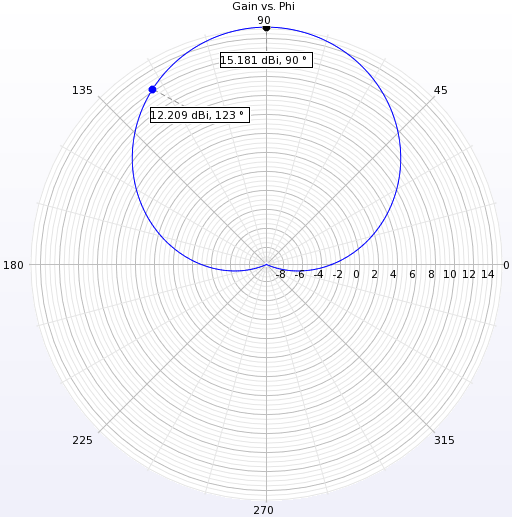
Figure 4: Far-zone pattern in the horizontal plane.
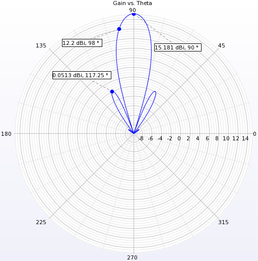
Figure 5: Far-zone pattern in the vertical plane.
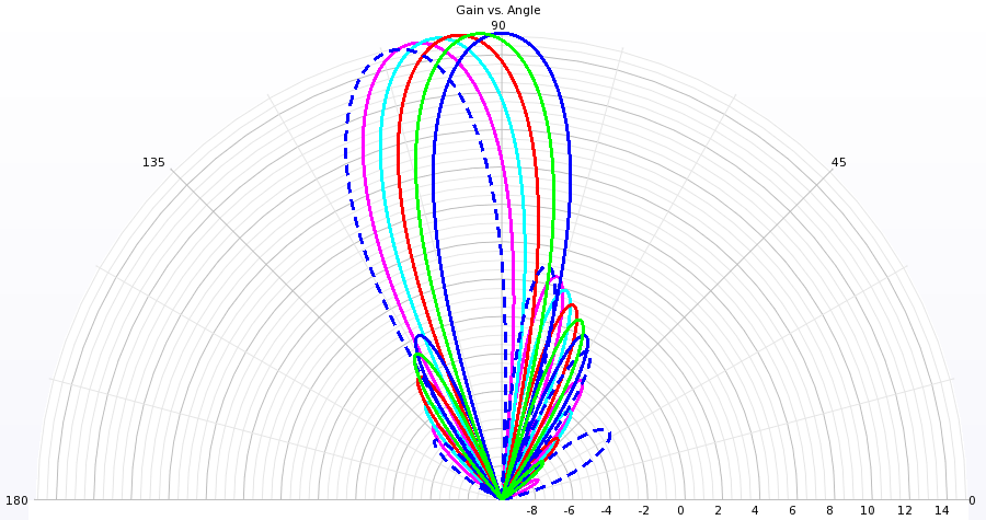
Figure 6: Vertical pattern for electrical downtilt every 3 degrees.
