.webp?width=1200&length=1200&name=detailed_5g_phone_patternv7%20(1).webp)


-

Webinars
Overview of XFdtd's Schematic Editor and Optimization for Matching Network Design
This webinar demonstrates the full range of features available to users, with a focus on recent updates that include optimization of component values, impedance and aperture tuners with tune codes, and system efficiency results.
See All Antenna Simulation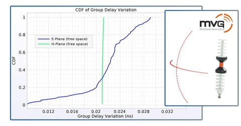
Webinars
Market Research Webinar: Group Delay for an Ultra Wide Band Antenna
In this webinar, XFdtd's product team discusses group delay for UWB antennas.
See All Antenna Simulation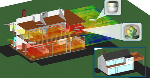
Webinars
Smart Home Device Design and WiFi Connectivity Using EM Simulation
This webinar demonstrates the strengths of Remcom’s XFdtd and Wireless InSite for designing and simulating smart home devices, analyzing propagation and beamforming capabilities, and assessing throughput performance of the devices via MIMO techniques.
See All Antenna Simulation -

Application Examples
60 GHz Phased Array Antenna Design and Beamforming Analysis Using XFdtd
In this example, explore a 60 GHz phased array antenna design using XFdtd, featuring full-wave FDTD simulation, beamforming optimization, and EIRP coverage analysis for WiGig applications.
See All Antenna Simulation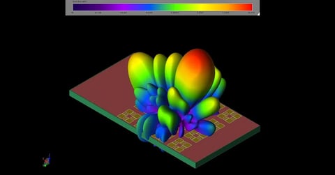
Application Examples
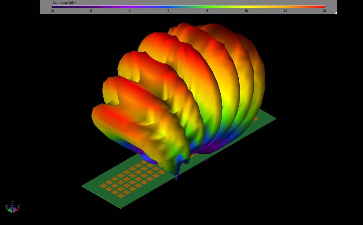
XFdtd Analysis of a Ku-band Satellite Antenna Array for Mobile Devices
In this example, a compact Ku-band antenna array is demonstrated for use in mobile device applications. The antenna is tuned for 12.5 GHz operation and contains a 4x4 array of elements which each consist of a set of patch antennas oriented and phased to produce a circularly-polarized far field pattern. The antenna array has peak gain over 20.7 dBi with sidelobes less than 8 dBi and a 3 dB beamwidth of about 15 degrees.
See All Antenna Simulation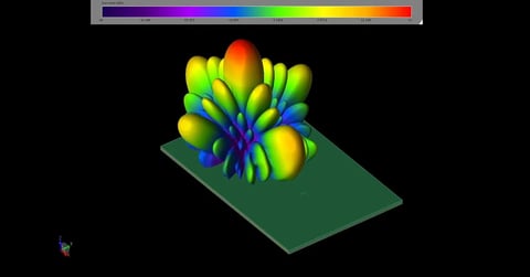
Application Examples
EM Simulation of 140 GHz Antenna Array for 6G Wireless Communication
A 140 GHz slot antenna array excited by a substrate integrated cavity is demonstrated for use in wireless communications. The antenna array has high gain, wide bandwidth, low fabrication costs, and small size, which make it an effective design. The final 8x8 antenna array has bandwidth from 130 to 145 GHz, peak gain of 20.5 dBi, and radiation efficiency around 60%.
See All Antenna Simulation -
Videos
Impedance Tuner Matching in XFdtd
This presentation will demonstrate the advantages of using XFdtd for complex matching network design.
See All Antenna Simulation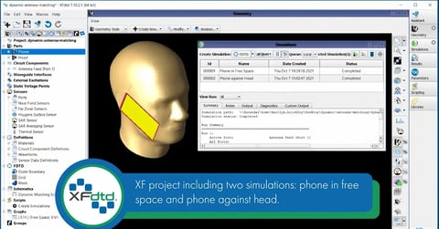
Videos
Dynamic Matched Antenna Using XFdtd’s Schematic Editor
In this video tutorial, an antenna's intrinsic impedance is simulated for two conditions--in free space and against a head. A three-port switch with two possible states is also included.
See All Antenna Simulation2.webp?width=480&height=251&name=maxresdefault%20(2)2.webp)
Videos
Tune a Tunable Matched Antenna Using XFdtd’s Schematic Editor
In this tutorial, we demonstrate the ease of adjusting or tuning, multiple operating modes so that capacitance values match various frequency bands. Using XF’s schematic editor with tuning slider bars, the correct values can be found in moments.
See All Antenna Simulation -

Publications
What’s New in XFdtd®
XFdtd Release 7.11.1 introduces several enhancements designed to elevate simulation accuracy, expand analysis capabilities, and streamline the engineering workflow. This release reflects Remcom’s continued focus on solving high-value challenges in antenna design, PCB modeling, and phased array system development.
See All Antenna Simulation
Publications
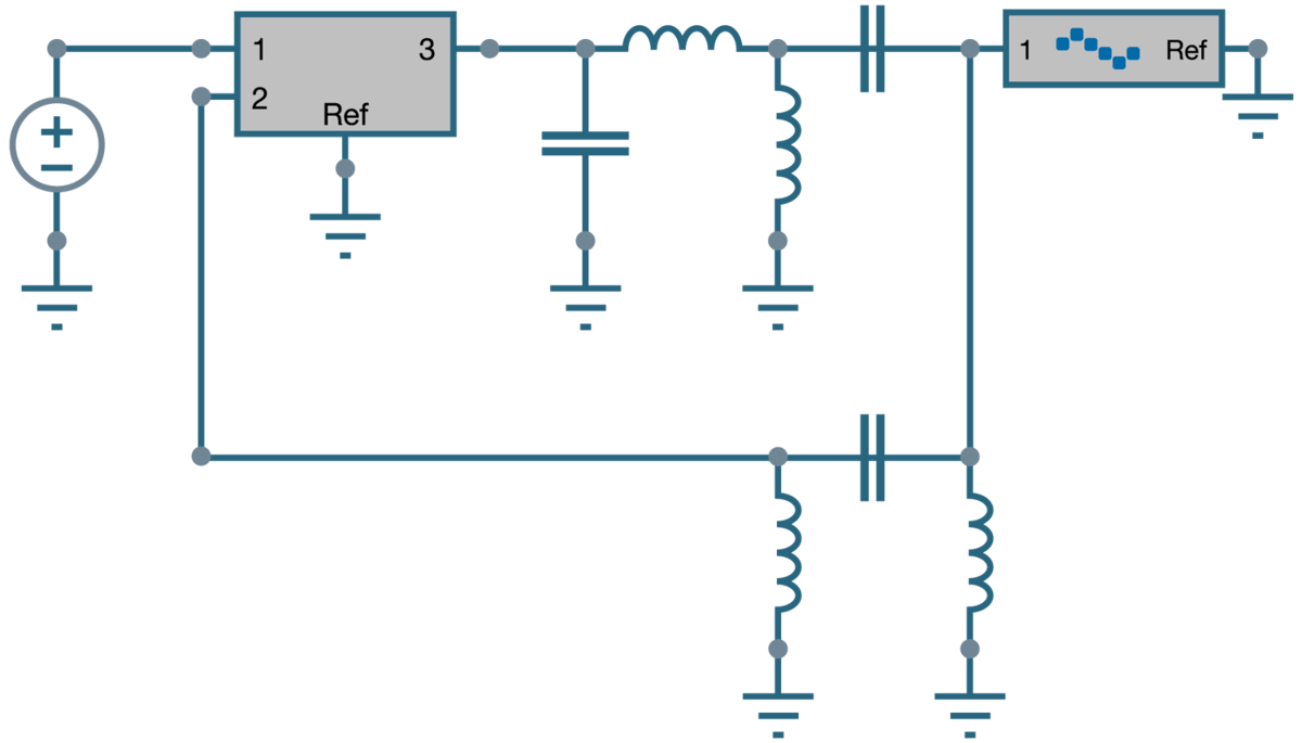
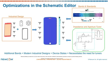
Mastering XFdtd’s Schematic Editor: A Comprehensive Overview
Dive into the capabilities of XFdtd’s schematic editor and discover how it transforms schematic creation, analysis, and optimization in engineering.
See All Antenna Simulation
Publications
Using Custom Antennas in IoT
Custom antennas are vital for seamless IoT connectivity, catering to diverse applications with specialized requirements.
See All Antenna Simulation
Save time and reduce costs.
Contact Remcom today for a customized solution to your most complex electromagnetic challenges.
Request a Quote