 Measurements of propagation path loss at 910 MHz in Ottawa, Canada were reported in the Whitekker paper [1]. This is probably one of the better papers reporting path loss measurements in an urban environment with low transmitting and receiving antennas. The measurements were made within the 1000 m x 600 m area in Figure 1. The transmitters were at a height of 8.5 m and the mobile receiving antennas were at a height of 3.65 m. All antennas were vertically polarized. Figure 1 shows a map of the area in which the measurements were made. More information on the measurements can be found in the original paper.
Figure 1: Map of Ottawa Showing Street Names and Transmitter Locations
The building data for the calculations were obtained directly from the maps in the Whitekker paper [1] which contained the footprints of the buildings. No specific information on building height was included, although the author's observation that the small buildings were typically three stories, and the large buildings were many stories, was used to create a more realistic looking building database. All calculations reported here were made using InSite's urban canyon model and no attempt was made to predict propagation over the buildings. No information about the terrain was included, and we have assumed a flat terrain in all our calculations.
Our method for extracting the building data from the published maps has led to a systematic enlargement of all buildings by a meter or so on each side. This has consequently led to slightly narrower street widths. This rather small error would not be a problem in many other urban areas, but due to the fairly narrow streets in this section of Ottawa, this may have been an additional source of error in the computations. We are currently attempting to obtain better building data for this area.
No information on building materials was reported. Following the suggestion in Tan and Tan [2], we set the relative permittivity of all the building walls to 7, and the conductivity to 0.2 S/m. A relative permittivity of 15 and a conductivity of 0.05 S/m were used for the ground.
Figure 2, Figure 3, and Figure 4 show the measured and calculated path loss along Laurier St., Albert St., and Queen St., respectively, with the transmitter at the Slater St. site. The route starts on Lyon and ends on Elgin. The free space path loss was included to demonstrate the large attenuation due to the buildings. The agreement is good considering the quality of the building data and the lack of information on building materials. It is worthwhile to comment on two of the more notable differences with the measurements.
Figure 2: Path Loss along Laurier St. with the Transmitting Antenna on Slater St
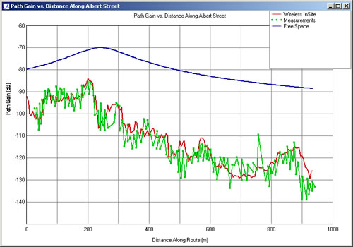
Figure 3: Path Loss along Albert St. with the Transmitting Antenna on Slater St.
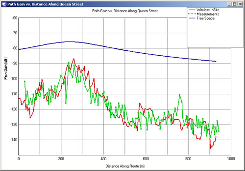
Figure 4: Path Loss along Queen St. with the Transmitting Antenna on Slater St.
First, the error at the beginning of Laurier St. is surprising because there is nearly a line-of-sight path from the transmitter. The predicted path loss is nearly at the free space value, while the measured path loss is 10 dB lower. One explanation is that there are some trees or other obstruction in the open area between Kent and Laurier.
Second, the differences between the measurements and the calculations at the beginning and end of Kent St. and Queen St. may be due to the absence on the map of the buildings along the right and left-hand edges of the area. If present, these building may have scattered a significant amount of energy from Slater St. up Lyon and Elgin Streets. Figure 5 shows the path loss along Bank St. with the transmitter at the Laurier St. site. The route starts on Nepean and ends on Wellington.
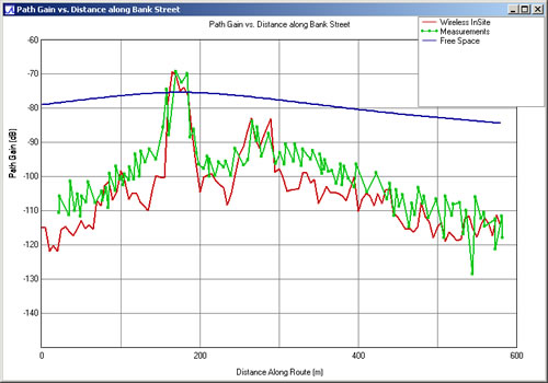
Figure 5: Path Loss along Bank St. with the Transmitting Antenna on Laurier St.
References
-
J. H. Whitteker, "Measurements of path loss at 910 MHz for proposed microcell urban mobile systems," IEEE Trans. Veh. Technol., vol. 37, no. 3, pp. 125-129, Aug. 1988.
-
S. Y. Tan and H. S. Tan, "Propagation model for microcellular communications applied to path loss measurements in Ottawa city streets," IEEE Trans. Veh. Technol., vol. 44, no. 2, pp. 313-317, Aug. 1995.