.png "matched-feed+(1)")
.png "image-asset (1)")

.png?width=250&height=307&name=image-asset%20(2).png "image-asset (2)")

.png?width=400&height=360&name=image-asset%20(3).png "image-asset (3)")

-
Webinars
Matching Network Design Updates in XFdtd
XFdtd includes a unique schematic editor that combines matching network analysis with full-wave results. Watch this webinar to learn about the latest advancements in the tool, including diplex matched antenna, microstrip-based components, SAR post processing, and frequency band specification.
Explore Resource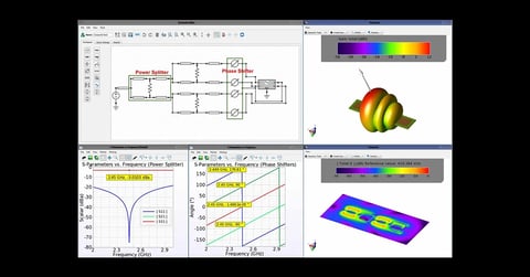
Webinars
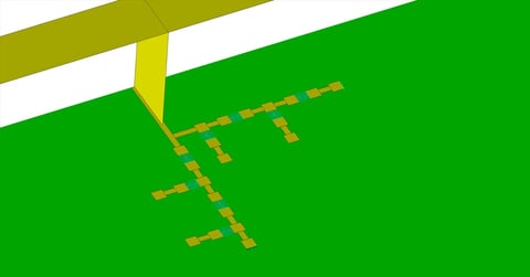
XFdtd’s Schematic Editor for Matching Network and Corporate Feed Network Analysis
Learn about XFdtd’s schematic editor and frequency-domain circuit solver for analyzing matching networks and corporate feed networks. We explore how to combine matching network analysis with full-wave simulation to view efficiency, near-field results, and far-zone patterns.
Explore Resource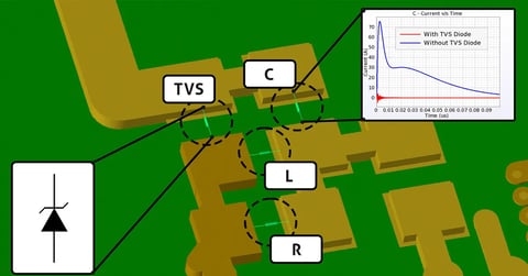
Webinars
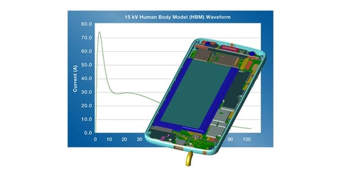
XFdtd’s Transient EM/Circuit Co-Simulation for TVS Diode ESD Protection
In this webinar, learn how XFdtd's transient EM/circuit co-simulation effectively resolves ESD vulnerabilities earlier in the design process and prevents future certification setbacks.
Explore Resource -
Application Examples
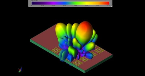
XFdtd Analysis of a Ku-band Satellite Antenna Array for Mobile Devices
In this example, a compact Ku-band antenna array is demonstrated for use in mobile device applications. The antenna is tuned for 12.5 GHz operation and contains a 4x4 array of elements which each consist of a set of patch antennas oriented and phased to produce a circularly-polarized far field pattern. The antenna array has peak gain over 20.7 dBi with sidelobes less than 8 dBi and a 3 dB beamwidth of about 15 degrees.
Explore Resource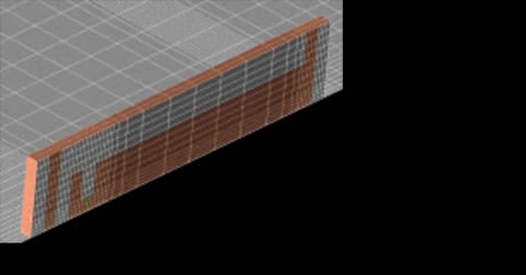
Application Examples
Printed PIFA Antenna Validation Data in Simulations
In this example a simple PIFA antenna is simulated and the return loss validated against measured data.
Explore Resource
Application Examples
Hip-Worn Cellular Telephone on Moving Man
The performance of a basic cellular telephone worn on the hip of a human male is studied for varying positions of the wearer.
Explore Resource -
Videos
An Overview of XFdtd's Schematic Editor for Matching Networks
This presentation covers XFdtd's capabilities for matching networks, including the schematic editor and frequency domain circuit solver.
Explore Resource.webp?width=480&height=251&name=maxresdefault%20(2).webp)
Videos
Simulation Software And The Need For A Schematic Editor
In this recording from Remcom's booth at the International Microwave Symposium, Justin Newton discusses how the schematic editor works and its benefits for complex antenna design.
Explore Resource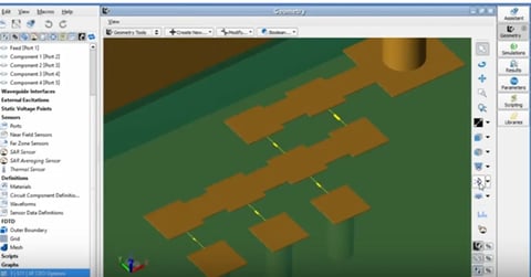
Videos
Demonstration of Full-Wave Matching Circuit Optimization in XFdtd
This video gives a demonstration of Full-Wave Antenna Matching Circuit Optimization using XFdtd's Circuit Element Optimizer (CEO). The antenna matching circuit design flow is discussed, including C
Explore Resource -
Publications
Transient EM/Circuit Co-Simulation in XFdtd: A Closer Look at TVS Diodes for ESD Protection
This paper introduces XFdtd’s transient EM/circuit co-simulation capability, which combines the strength of 3D full-wave electromagnetic simulation with the flexibility of circuit solvers.
Explore Resource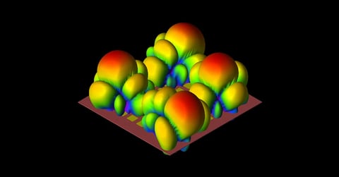
Publications
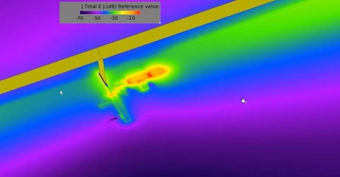
XFdtd Analyzes Complex Beam Steering with Antenna Array Simulation
In this article from the July 2020 issue of Microwave Journal, we demonstrate how XF’s superposition and array optimization features simplify the process for understanding device performance by providing efficient ways to validate array coverage.
Explore Resource
Publications
Using EM Simulation for 5G Design E-Book
Download examples that demonstrate how EM simulation software solves challenges related to 5G and MIMO. Examples include MIMO and array design, 5G urban small cells, mmWave and beamforming.
Explore Resource
Save time and reduce costs.
Contact Remcom today for a customized solution to your most complex electromagnetic challenges.
Request a Quote