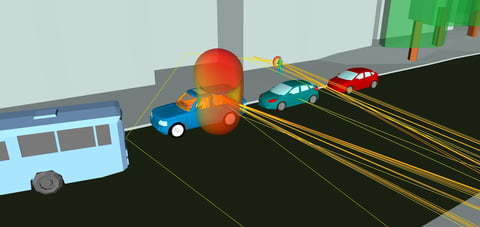
Today’s military works in a complex electromagnetic arena. IED jammers and UGS systems are examples where propagation is very near to the ground, and the interaction of signals with the earth can unintentionally alter propagation. In these scenarios the direct and reflected waves tend to cancel one another, causing the surface wave component to be the dominant mode of propagation. This surface wave must be taken into account in order to correctly model propagation of radio waves in these cases.
Many methods of studying propagation do not incorporate the effects of subterranean layers of different materials. This paper demonstrates that subterranean layers can greatly impact near earth propagation. Radio propagation predictions made by Norton, XFdtd®, and the moving window finite difference time domain (MWFDTD) methods are used to analyze propagation for near-ground antennas over various types of layered media.
Introduction
The complex electromagnetic environment faced by today’s military forces is a challenge to manage and accurately model. On one hand, the jammers used to disable improvised explosive devices (IEDs) can interfere with a wide range of tactical communication systems. On the other hand, signals from battlefield radio systems can render IED jammers ineffective. These systems, as well as unattended ground sensors (UGS) and other modern military applications, are employed near to the ground. This proximity to the earth greatly affects the propagation of the signal, and must be properly modeled when designing equipment and planning communication
systems.
A variety of methods have been applied to the prediction of near-ground radio propagation over irregular terrain. For the widely used ray-based models, it is recognized that the results must be based on several levels of approximations, which typically include approximate reflection and transmission coefficients. Although ray methods are able to model propagation both above and beneath the surface, they cannot model the surface wave. The Norton-Sommerfeld surface wave formulas and the Parabolic Equation method can be applied to surface wave propagation over a smooth, homogeneous, lossy ground; however the impedance boundary condition methods are not valid for layered media. A full wave approach to modeling radio wave propagation based on the extended finite difference time domain (FDTD) method can accurately account for all of the aforementioned effects for near-ground antennas. The use of a full wave method also eliminates the need to make many of the approximations that other methods require, and can support detailed modeling of complex antenna designs and the ground.
Of particular interest is the interaction of the electromagnetic energy and the layered media that are used in road construction. Because the skin depth at certain low VHF frequencies is often larger than the depth of the surface material, modeling the roadbed layers is required. At these frequencies over distances of a few hundred meters, the surface wave component of near-ground radio systems can be significant for some materials and not others. FDTD based methods allow detailed modeling of the propagation effects caused by the roadbed layers.
This paper uses two full-wave models and the Norton model to predict the propagation loss for near-ground antennas over flat roadbeds. Several types and configurations of roadbed construction materials are considered, exhibiting layers of different thicknesses, and electric properties. The propagation path loss is computed and compared, demonstrating that subterranean layers affect the near earth propagation.
Surface Wave Phenomenology
The surface wave results from electrical currents induced in the ground by refraction of a reflecting radio wave. The phenomenon is most obvious when the transmitter and receiver are close to the ground, separated by a relatively large distance. In such situations, the reflected and direct waves are out of phase by 180o and cancel one another. The resulting field intensity is primarily due to the surface wave [10]. The phenomenon was first observed over a hundred years ago by Arnold Sommerfeld [9] and others, with mathematical corrections being given by Norton [8] and careful experimental measurements carried out by Burrows [5] in the 1930s.
The effect of subterranean layers on surface waves was studied by Wait [11][12][13][14][18][21] and King and Sandler [6][17][19]. Using a surface impedance method, and after much debate, they were able to derive analytical formulas for the prediction of the electrical fields at all points over a layered half plane without having to resolve the field within the layers. They described how a surface wave can be excited by a dipole near to the earth.
Propagation Models
This study uses two full wave FDTD models and a simpler Norton model to make propagation predictions. These models were chosen as a representative of two different theoretical approaches to modeling.
Full wave FDTD models are the most accurate, physically based models. The approach is to solve Maxwell’s equations in the time domain. Two examples of an FDTD model were used here: XFdtd® and MWFDTD, both Remcom products.
With XFdtd, a large volume containing the transmitter, subterranean layers, and the entire range of interest is
divided into an evenly spaced rectangular grid. In addition, time is divided into even intervals. To begin the simulation, an electromagnetic pulse is excited at the transmitting antenna. At each time step, the second-order finite differencing method of Yee[3] is used to solve Maxwell’s equations to determine the electromagnetic fields at each grid point.
The benefit of using XFdtd is the accuracy of the model, the ability to model an arbitrary number of levels and types
of dielectric materials. In addition, XFdtd can be used to make animations of the propagation, and can resolve the surface currents of interest in this problem. The drawback to using XFdtd is that as the study space gets large, calculation time and memory requirements can grow impractically large.
The MWFDTD propagation model simulates the radio wave propagation in the 2D vertical plane, by using a modified FDTD method [4]. It takes advantage of the fact that the propagating radio pulse is limited in spatial extent, by limiting the computational grid to include only the pulse. As the pulse propagates along the terrain, the computation mesh is moved to follow along with the pulse. It is also able to model sub-surface layers of different dielectric material. This enables one to achieve high fidelity results for spatially extended applications. It can also be used to make animations that help in analyzing the phenomenon.
MWFDTD can directly model the following physical effects:
-
Scattering from small-scale surface roughness
-
Scattering and blockage by larger scale irregularities
-
Blockage and absorption by vegetation assuming effective permittivity model (usually valid at < 1000 MHz)
-
Surface waves over irregular ground
-
Stratified ground
-
Broadband results from a single run including frequency dependence of ground permittivity
-
Effect of ground in the near-field of the transmitting antenna
In addition to these high fidelity models, a comparison was made, in the case of single layered terrain, to the Norton method. This model is based on the Norton’s corrections to Sommerfeld’s theory of surface waves [8].
Study Parameters
The losses are studied in the lower ten meters of the atmosphere over a path 200 meters long. In all cases the terrain was flat. The transmitter was a vertical dipole located 2m above the ground, transmitting at 145 MHz.
To study the surface wave, first three simple cases of dry asphalt were studied with all models. These cases varied in conductivity alone. The relative permittivity was fixed at ε = 4.3, while the conductivities were σ = 0.06, 0.00073, and 0.00089 S/m. The dielectric properties of the materials used in this study are given below in Table 1s.
More complicated cases of layered terrain were studied with XFdtd and MWFDTD. The goal was to model a variety of typical roadbeds ranging from a two-layered asphalt and concrete road to a multilayered reinforced concrete road. In addition, two cases of road built over swampy, marshy ground were simulated.
Results
We will first compare the results of MWFDTD, XFdtd and the Norton model. The first plot compares path loss at a height of 1m above ground as a function of range for each model. In this case, the frequency is 100MHz, and the surface material is Asphalt1. As can be seen, the three models are in close agreement, showing a gradual attenuation with range.
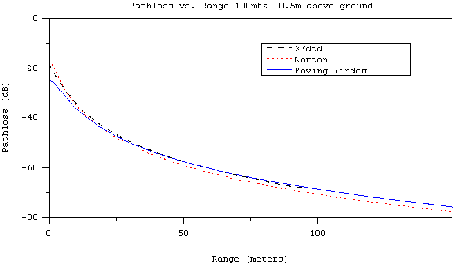 Figure 1: Path loss at a height of 0.5m above ground for XFdtd, MWFDTD, and Norton. Propagation over dry asphalt at 100MHz.
It is also illustrative to view the entire vertical plane. The following coverage plots show path loss as a function of position for the vertical plane containing the transmitter and receiver. The color scale is fixed at a dB range of 0 to 90.
The first three images show the path loss predictions made by the three different models at 145 MHz, for dry asphalt (σ = 0.06 S/m). As can be seen, the three models agree well close to the surface, differing significantly from one another only as height increases.
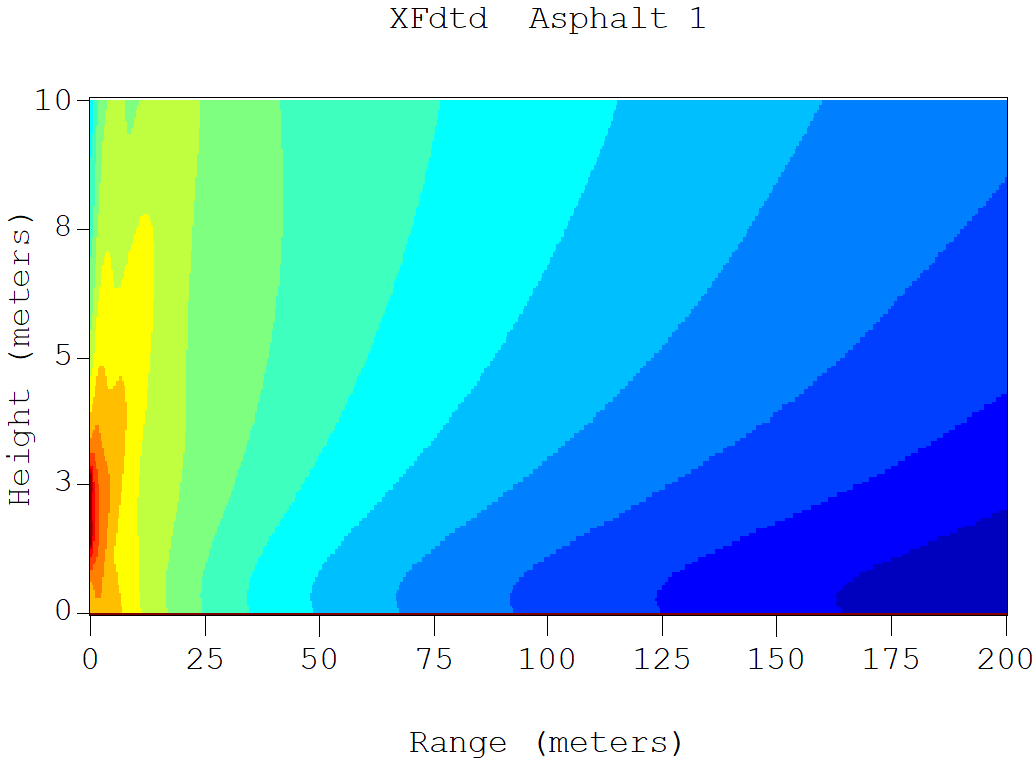
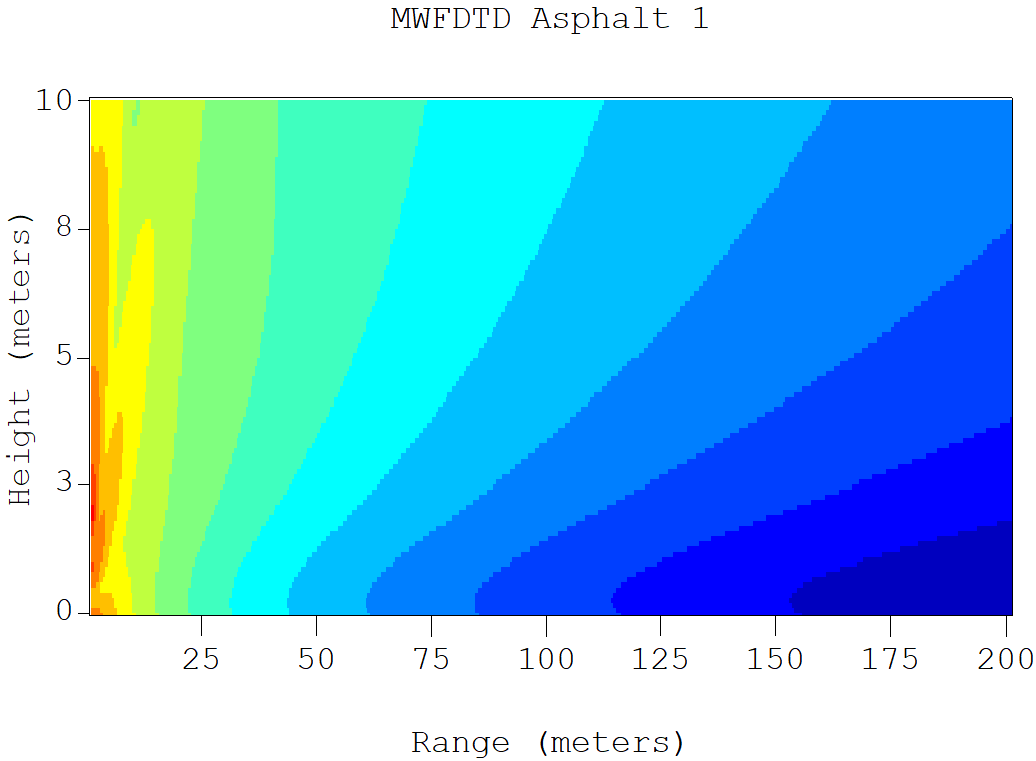
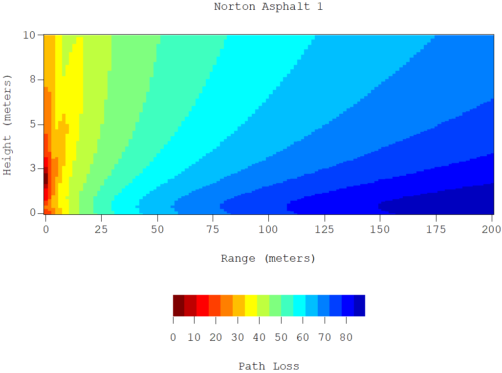 Figure 2: Path loss prediction over dry asphalt (σ = 0.06) using XFdtd, MWFDTD, and Norton.
The next three images show propagation over three types of asphalt, which differ only in conductivity. MWFDTD was used for all of these runs. This illustrates the effect that the dielectric properties of the terrain have on the propagating wave. The effect is pronounced within the lowest meter above the ground.
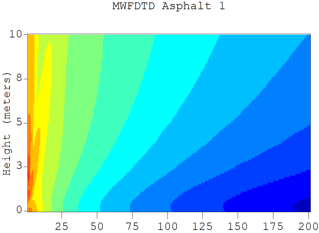
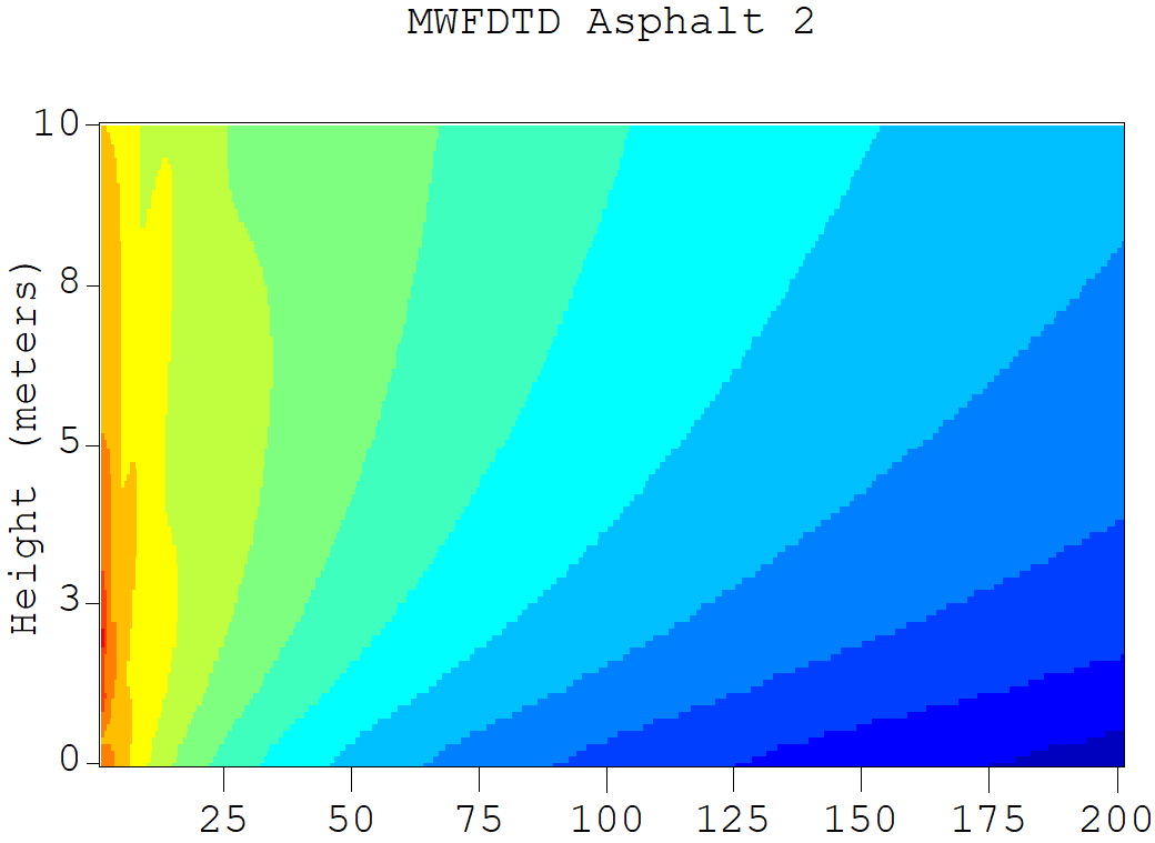
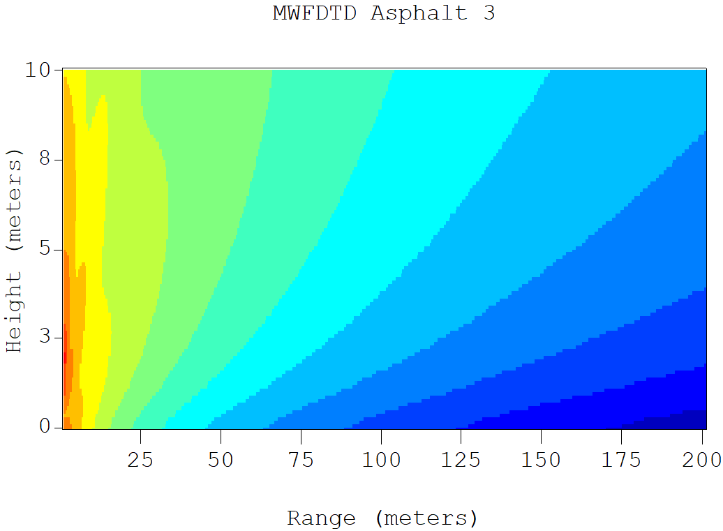 Figure 3: A comparison of path loss for asphalt 1 (σ = 0.06), asphalt 2 (σ = 0.00087), and asphalt 3 (σ = 0.00017).
Road construction techniques can vary widely and have a great effect on near earth propagation. Here we will compare the path loss for different types of roadbed: a solid concrete slab, a two-layer concrete road, and two reinforced concrete roads (see Figure 4).
The solid concrete slab was 0.6 m thick. The two-layered concrete road was modeled with a 0.3 meter asphalt layer over 0.3 meters of concrete. Two thicknesses of reinforced concrete were chosen such that in one case the concrete layer was thicker than the skin depth, and in the other case it was thinner than the skin depth. The layer was 0.1 meters thick for the thin reinforced concrete, and 0.4 meter thick for the thick reinforced concrete. The skin depth for asphalt at 145 MHz is about 0.19 meters.
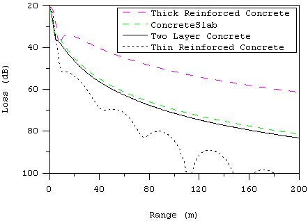 Figure 4: Path loss at a height of 1m above ground as a function of range for various concrete roadbeds.
It is worth pointing out that concrete roads are typically reinforced by placing heavy-gage steel wire, which has been welded into mesh-like sheets, into the concrete before it has cured. Using MWFDTD, this steel mesh was modeled with a perfect electric conducting (PEC) backed material. Simulations using XFdtd are able to account for the actual dimensions and spacing of steel dowels and tie bars also typical of road construction.
The last part of this study is an examination of the effect of subterranean layers on near earth propagation. The materials were chosen to model roads built over damp or marshy soil or in areas with a high water table. Figures 5 and 6 illustrate the effect of subterranean layers on the propagation. In the first case XFdtd was used to model a half wavelength dipole over wet soil (ε = 8, σ = 0.04). In the second case, the road is made up of 0.15 m of Asphalt 1 over 3.82m of wet soil.
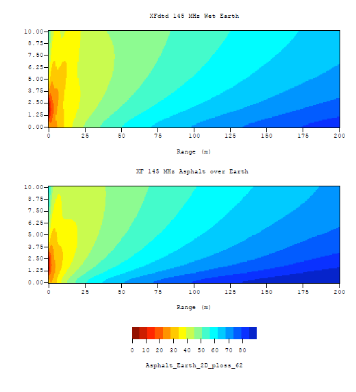 Figure 5: Path loss for wet soil (top) and asphalt over wet soil (bottom), 145 MHz, using XFdtd.
Figure 6 shows the path loss at a height of 1m vs. range for a thin (0.1m thick) asphalt road over marshland, a thick (0.4m thick) asphalt road over marshland, and a solid asphalt road. Figure 7 illustrates how the presence of seawater with its high conductivity has an overwhelming influence on the propagation, even when the water is below the surface.
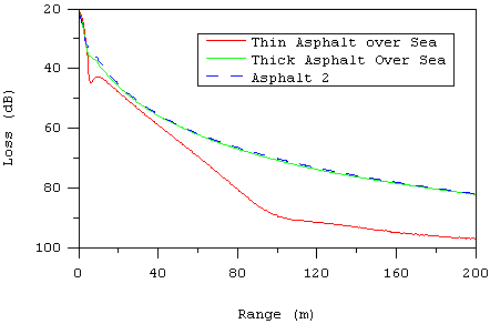 Figure 6: Path loss at a height of 1m above ground as a function of range for various roadbeds over marshland.
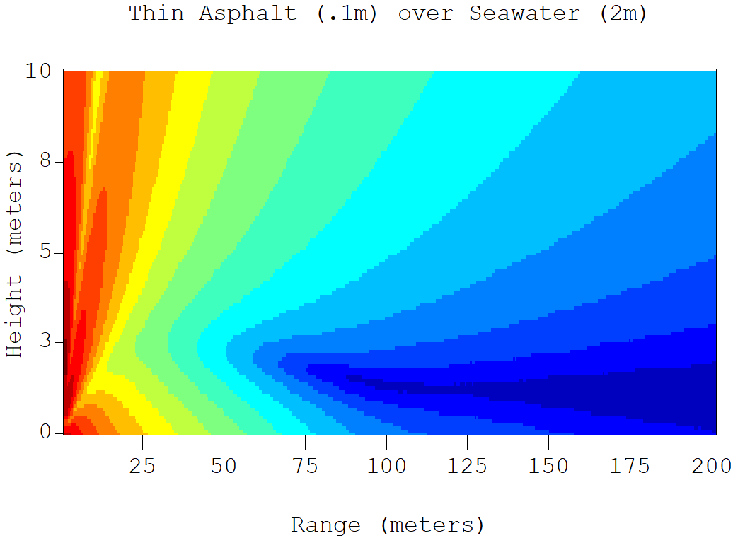 Figure 7: Path loss prediction over .1m asphalt on top of 2m seawater.
Future Work
In addition to providing more accurate simulations of the scenarios examined here, the use of XFdtd will enable a detailed study of the surface wave mechanism. XFdtd can resolve the surface currents for these and other geometries. By analyzing animations of the surface currents, a better understanding of the surface wave phenomenon can be achieved.
Conclusions
The three methods used in this paper are in agreement in their prediction of path loss in near to ground propagation scenarios over layered media.
It has been demonstrated that subterranean layers of varying materials can greatly impact the near to earth propagation. In particular the variations in road construction techniques can be a big factor in near earth propagation scenarios. IED jamming efforts need to take into account subsurface materials in order to correctly predict the RF environment.
References
-
A. Cotcher, “Radio-Broadcast-Transmitter Location: Metropolitaan Boston as an Illustrator,” Georgraphical Review. Vol. 38, No. 2, pp. 271-277, 1948.
-
Barlow, H.M. “Surface Waves.” Proceedings of the I.R.E. 46 (1958): 1413-1417.
-
Yee, K. S., “Numerical solution of initial boundary value problems involving Maxwell’s equations in isotropic media,” IEEE Trans. Antennas Propagat., vol. 14, pp. 302-307, 1966.
-
Luebbers, R.; Schuster, J.; Wu, K., "Full wave propagation model based on moving window FDTD," Military Communications Conference, 2003. MILCOM 2003. IEEE , vol.2, no., pp. 1397- 1401 Vol.2, 13-16 Oct. 2003.
-
Burrows, C.R., "The Surface Wave in Radio Propagation over Plane Earth," Proceedings of the IRE, vol.25, no.2, pp. 219-229, Feb. 1937.
-
King, R. J., “EM Wave Propagation Over a Constant Impedance Plane,” Radio Science, 4, 1969, pp 225-268.
-
Maclean, T.S.M. and Z. Wu. Radiowave Propagation Over Ground. Chapman & Hall. London, 1993.
-
Norton, K. A. “The Physical Reality of Space and Surface Waves in the Radiation Field of Radio Antennas.” Proceedings of the I.R.E. 25 (1937): 1192-1202.
-
Sommerfeld, A. N., “Propagation of Waves in Wireless Telegraphy,” Ann. Phys. (Leipzig), 28, 1909, pp 665-737.
-
Soutsos M. N., Bungey J.H., Millard S.G., Shaw M.R. & Patterson A., "Dielectric properties of concrete and their influence on radar testing", NDT&E International, Vol. 34, 2001, pp 419-425.
- Wait, J. R. Electromagnetic Waves in Stratified Media. Pergamon Press. Oxford, New York. 1970.
-
Wait, J. R. “On the Pulse Response of a Dipole over an Impedance Surface”1973 Antennas and Propagation Society International Symposium 11 (1973): 433-436.
-
Wait, J. R. “Propagation Effects for Electromagnetic Pulse Transmission.” Proceedings of the I.R.E. 74 (1986): 1173-1181.
-
Wait, J.R., "The ancient and modern history of EM ground-wave propagation," Antennas and Propagation Magazine, IEEE, vol.40, no.5, pp.7-24, Oct 1998.
-
Wilson, J., Whittington, H., “Variations in the Electrical Properties of Concrete with Change in Frequency,” IEE Proceedings, vol. 137, pt. A, no. 5 (1990): 246-254.
-
Collin, R. E., “Hertzian Dipole Radiating Over a Lossy Earth or Sea: Some Early and Late 20th -Century Controversies,” IEEE Antennas and Propagation Magazine, vol. 46, no. 2 (2004): 64-79.
-
King, R. W., Sandler, S. S., “The electromagnetic field of a vertical electric dipole in the presence of a three-layered region,” Radio Science, vol. 29, no. 1, pp. 97-113, January-February 1994.
-
Wait, J. R., “Comment on ‘the electromagnetic field of a vertical electric dipole in the presence of a three-layered region,’” Radio Science, vol. 33, no. 2, pp. 251-253, March-April 1998.
-
King, R. W., Sandler, S. S., “Reply to ‘comment on the electromagnetic field of a vertical electric dipole over the earth or sea,’” Radio Science, vol. 33, no. 2, pp. 255-256, March-April 1998.
-
Fei, T., Li, L., Yeo,T., Wang, H., Wu, Q., "A Comparative Study of Radio Wave Propagation Over the Earth Due to a Vertical Electric Dipole," IEEE Transactions on Antennas and Propagation, Vol. 55, no. 10, pp. 2723-2732, Oct. 2007
-
Wait, J. R. “Transient Fields of a Vertical Dipole over a Homogeneous Curved Ground.” Can. J. Phys., vol. 34 (1956): 27- 35.