Designing physical structures that exhibit a zero degree phase shift in the reflection coefficient presents a particularly interesting challenge. Although in theory, this is the behavior of a Perfect Magnetic Conductor (PMC), PMC materials do not exist in nature. If designed correctly, these metamaterials promise to improve antenna performance while decreasing overall size. Dr. Makino of Kanazawa Institute of Technology has made progress in this area by using a double-ringed periodic structure. The structure of Figure 1, which exhibits the reflection phase of PMC at 9.5 GHz, was originally designed, fabricated, and tested in his laboratory. Later, it was simulated in XF and good agreement was found.
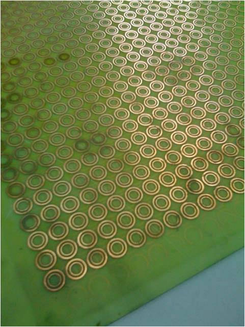
Figure 1: The fabricated double-ringed periodic FSS structure.
Two frequency selective surface (FSS) structures were fabricated and measured; the periodic double-rings of Figure 2 were present on the surface of both. For Case I, the FSS contained a single substrate layer with a thickness of 0.564 mm, while Case II contained an additional spacer layer and was backed with a metal plate for a total thickness of 5.264 mm.
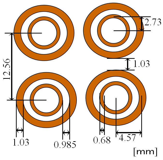
Figure 2: Dimensions of the rings.
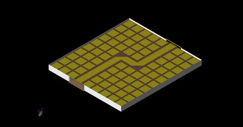
For the XFdtd simulations, only a single double-ring unit was modeled in each case, as shown in Figures 3 and 4. Periodic boundary conditions were applied to the units during the calculation to better represent the fabricated structure while reducing memory and run time requirements. A linearly polarized plane wave was incident normally to the periodic structure to match the measurement conditions and scattered fields were collected.
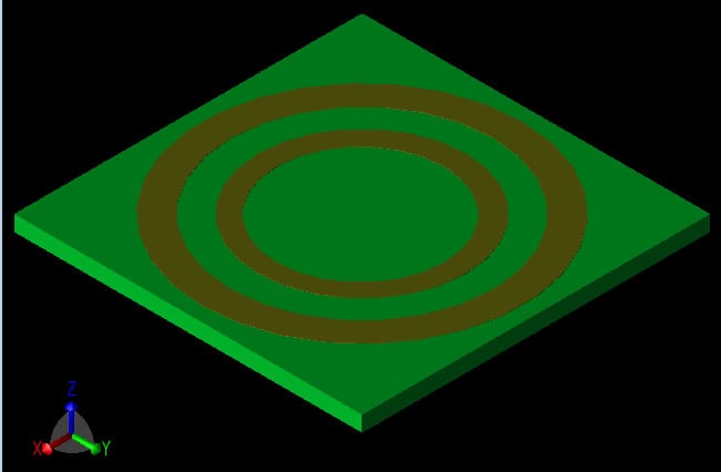
Figure 3: Unit cell of Case I: FSS structure.
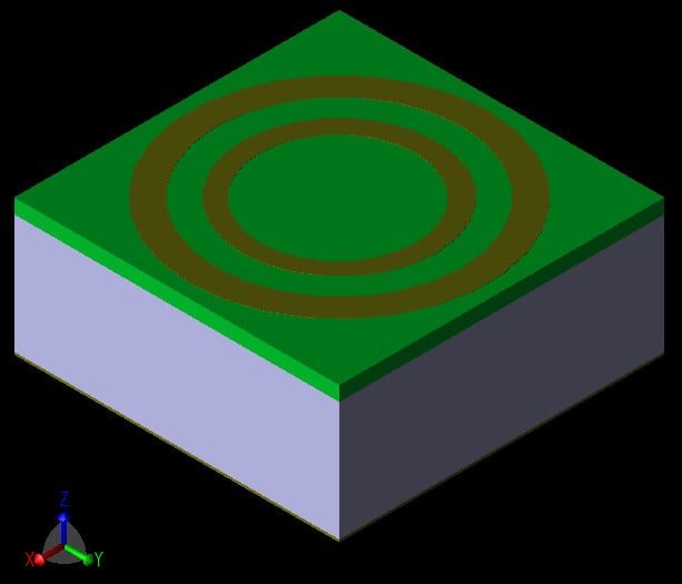
Figure 4: Unit cell of Case II: metal backed FSS structure.
Transmission coefficients were computed for Case I and compared against measurements as shown in Figures 5 and 6.
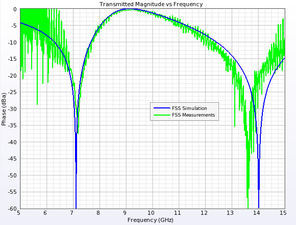
Figure 5: Transmission coefficient magnitudes for Case I.
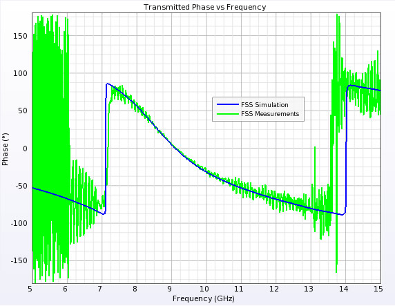
Figure 6: Transmission coefficient phases for Case I.
The reflection coefficient phase was computed for Case II and compared against the fabricated, metal backed FSS as shown in Figure 7. This figure shows that the structure is well designed and has a zero degree reflection phase, like PMC, at 9.5 GHz.
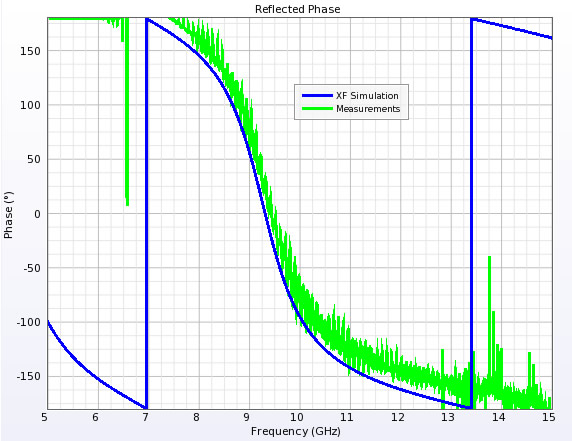
Figure 7: Reflection coefficient phases for Case II.
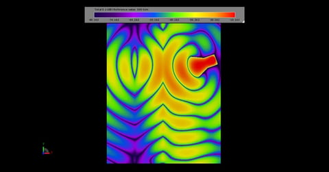
An additional Case II simulation was run with three unit cells and steady state electric fields were saved at 9.5 GHz. Figure 8 shows the non-uniform field distribution at the surface of the metal backed FSS. If this structure were being used for a low profile antenna, this distribution should be considered when determining the height of the radiator above the reflector.