This is a 7-11 GHz stripline Wilkinson power divider, a common microwave signal splitter design to maximize isolation between the output ports. Prominent elements of a 50 ohm equal-split Wilkinson divider include quarter-wave transmission line sections and a 100 ohm isolation resistor [1].
This planar Wilkinson divider uses waveguide ports and a planar resistor implemented with a lossy dielectric specified in terms of conductivity. Figure 1 shows the structure of the power divider. The distance between the receive ports is 19.94 mm and the distance from the source to the far conductor is 15.57 mm. The substrate has a dielectric constant of 2.94 and dimensions of 16.128 mm long (x), 19.936 mm wide (y), and 1.52 mm thick (z).
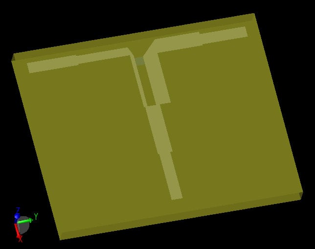
Figure 1: Wilkinson divider including substrate, stripline, isolation resistor, and waveguides interfaces.
As in any FDTD simulation, the accuracy of the results is dependent on how well the grid matches the model geometry. The gridding properties of the stripline are set so grid lines automatically align with its edges and XACT Accurate Cell Technology® is enabled for the diagonal portions so the errors due to staircasing are reduced. Figure 2 shows the resultant mesh in the plane of the stripline.
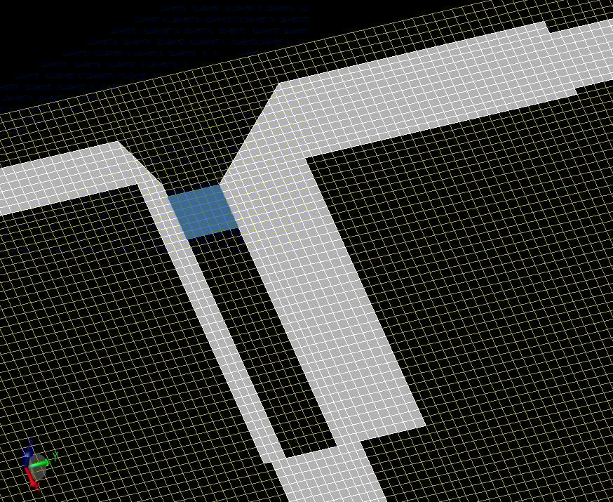
Figure 2: Mesh representation of the power divider with automatic gridding and XACT enabled.
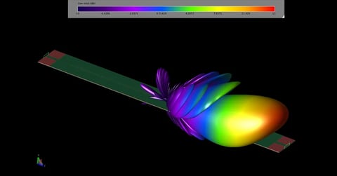
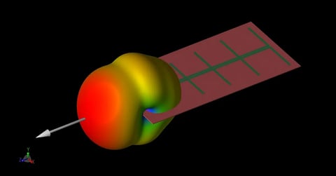
A broadband simulation is run to generate S-parameters from port 1 to the two split output ports 2 and 3. Figure 3 shows a wide band of operation for this power divider. Steady state surface currents are also computed at 10.067 GHz, as seen in Figure 4.
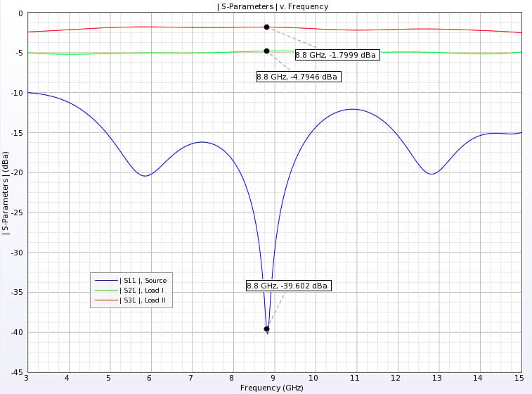
Figure 3: S-Parameter results for the three ports.
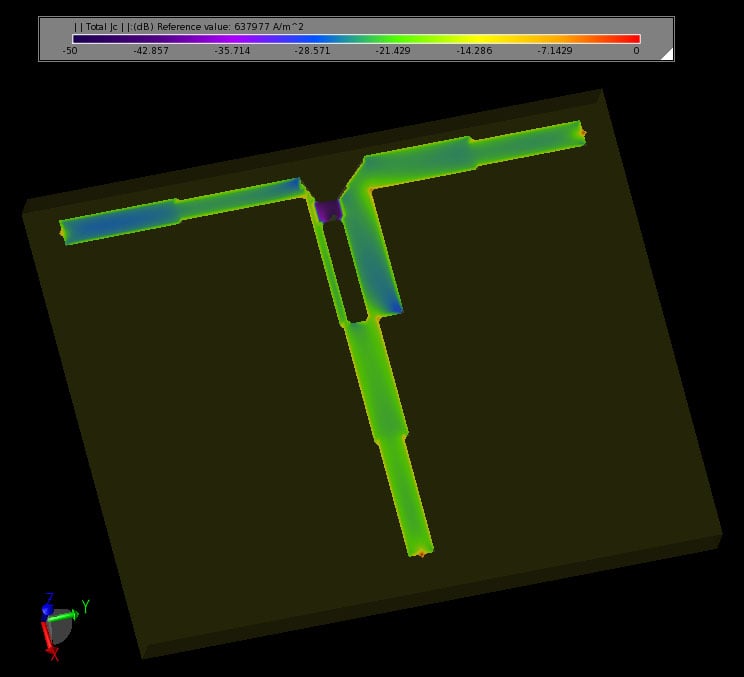
Figure 4: Steady state surface currents on the stripline at 10.1 GHz.
Reference
-
David M. Pozar, Microwave Engineering, 2nd ed, New York: John Wiley & Sons.