Accurate calculation of RCS at millimeter wave frequencies requires sufficiently detailed geometric representation of the target and physical modeling techniques that capture the scattering effects of small facets. Highly detailed facet models and traditional methods for calculating RCS at these frequencies can often result in very long run times. Using Remcom’s X3D with Physical Optics (PO) and Method of Equivalent Currents (MEC) model for calculating RCS, accurate results can be achieved within reasonable run times.
This example details the setup and execution of RCS calculations using XGtd’s X3D PO MEC model and compares the predictions to those made using XFdtd.
The target is a Hellfire missile, which was imported into XG from a KMZ file. Figure 1 shows the Hellfire geometry, which has 11,536 facets and is modeled as PEC material. No simplification of the geometry is required, though it is expected that geometry imported into XG will be well formed without unintentional holes or gaps in the facet data. The missile is oriented with the nose pointed in the positive x-direction, with launch guides in the positive z-direction. Figure 2 shows the missile from each of the three cut planes.
Figure 1: Hellfire missile geometry
Figure 2: Hellfire missile viewed from the XY, XZ, and YZ cut planes
For the simulation, the X3D RCS model is selected, with Physical Optics and Method of Equivalent Currents calculation methods both enabled. The allowed interactions are one reflection and one diffraction. Note that for the X3D model, this means that paths will be found with up to one reflection and one diffraction on the way to the target scattering surface as well as on the return from the target, resulting in paths with up to twice as many interactions in addition to the scattering surface integration (a total of up to five interactions).
Three plane waves are defined for the XY, XZ, and YZ cut planes, each with a full 360 sweep and one degree spacing, as indicated in Figure 3. A 10 GHz sinusoidal waveform is used. Two far zone requests (for phi- and theta-polarization) are defined for each plane wave, resulting in six monostatic RCS far zone requests.
Figure 3: Hellfire missile with cut planes
Results
The predictions made by XG’s X3D RCS model were compared to results generated by XF. The XF simulations were performed using 30 cells per wavelength and required parameterization and scripting to assemble the results into a single plot file for each cut plane.
Figures 4, 5, and 6 show the comparison between XG’s X3D model and XF for the theta-polarized RCS predictions, and Figures 7, 8, and 9 show the comparisons for the phi-polarized predictions. Tables 1 and 2 give the error statistics for theta- and phi-polarization respectively. The plots and quantitative statistics show very good agreement between the two models, with a mean error ranging from -0.6911 to 0.774 for theta-polarized RCS and from -0.1854 to 1.58 for phi-polarized RCS.
Figure 4: Theta-polarized RCS in XY plane: comparison of X3D PO MEC (red) and XF (black)
Figure 5: Theta-polarized RCS in XZ plane: comparison of X3D PO MEC (red) and XF (black)
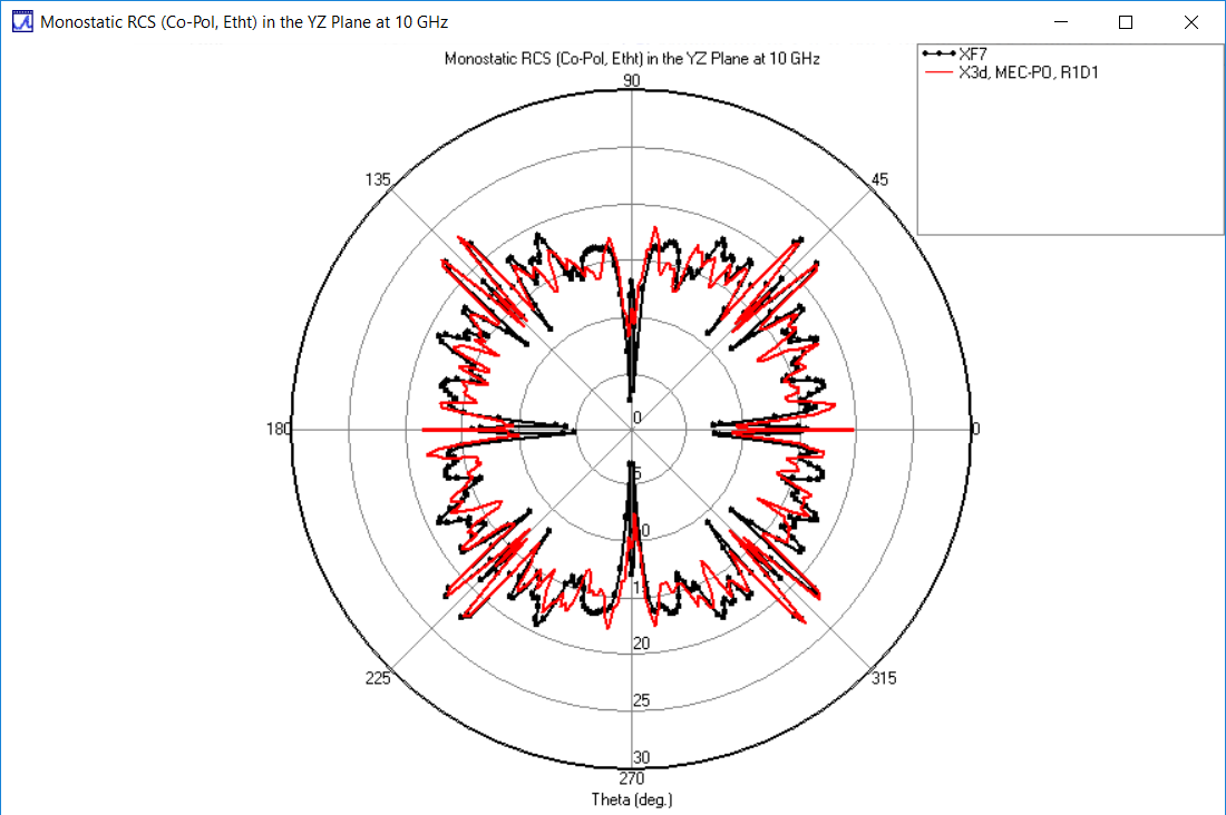
Figure 6: Theta-polarized RCS in YZ plane: comparison of X3D PO MEC (red) and XF (black)
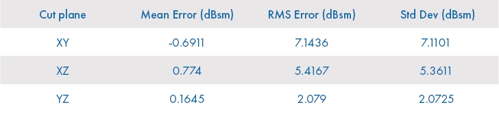
Table 1: Error statistics comparing XG to XF for theta-polarized RCS of Hellfire missile
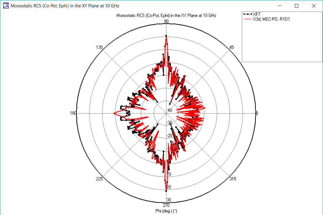
Figure 7: Phi-polarized RCS in XY plane: comparison of X3D PO MEC (red) and XF (black)
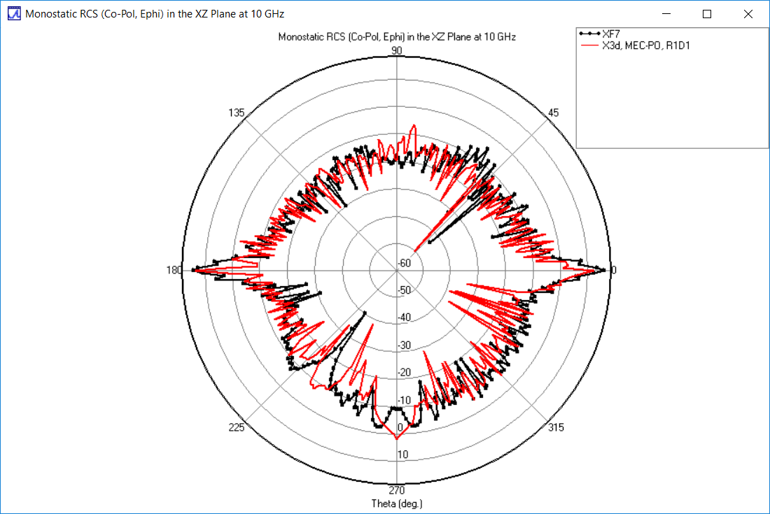
Figure 8: Phi-polarized RCS in XZ plane: comparison of X3D PO MEC (red) and XF (black)
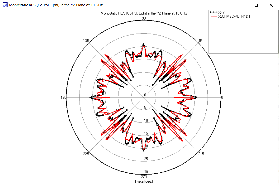
Figure 9: Phi-polarized RCS in YZ plane: comparison of X3D PO MEC (red) and XF (black)
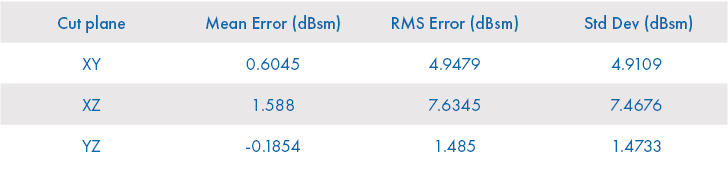
Table 2: Error statistics comparing XG to XF for E-phi RCS of Hellfire Missile
The simulations in this example were performed on a single workstation with four cores and a moderate-level GPU. Run time was approximately 13 seconds per monostatic angle, requiring just over an hour to complete each 360° cut.