Modeling communication systems within enclosed spaces such as culverts, mines, or tunnels can be difficult due to interactions that are present in the enclosed space. These complicated interactions include multiple reflections, multiple ground bounces, diffractions around corners, etc. Each of these interactions is a vital element to accurately calculating the received power. Remcom’s Wireless InSite not only models each interaction but provides an efficient, streamlined way of creating an enclosed model.
Communication analysis that focuses on culverts or other enclosed space is important because the environment around the system is very different than in more open areas. Communication with various portions of a culvert is vital to ensure the safety and efficiency of the operation. Knowing how the communication equipment will perform in the actual scenario helps design engineers to ensure coverage for the whole culvert.
One application where accurate communication is necessary is during a mine rescue operation where communication with trapped personnel or rescue teams is vital. Another application is automated guided carts or vehicles within the mine which carry personnel, equipment, or products to and from various parts of the mine. These are just a few of the applications that require a reliable communication system within the mine or culvert. Modeling these scenarios before installing equipment is critical for correctly designing these systems. It saves time by allowing the ability to modify various inputs to achieve the best possible solution before the heavy, expensive equipment is purchased and actual measurements are taken.
Wireless InSite has a culvert design wizard available under the Extensions tab in the Preference Window. The Creation Window allows for culverts to be defined at any length, any diameter, 4- to 32-sided, and a single bend of 0, 45, -45, 90, or -90 degrees.
In this example, a straight, square culvert will be created using the Wireless InSite culvert design wizard and a transmitter will be placed at the entrance to the culvert. Then a coverage plot of the results will be shown which will provide results throughout the culvert to determine how well the transmitter can communicate. All of these steps can be easily and efficiently performed in Wireless InSite, more quickly than measuring data in the field. The results given by Wireless InSite have been shown to correspond well with measured data[1].
Figure 1 shows the Creation Window. A 30m, 4-sided straight culvert is defined. The material assigned is Wet Earth, the definition of which can be found in the material library provided within Wireless InSite. Figure 2 shows the culvert within the software.
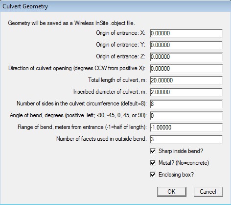
Figure 1: Culvert Modeling Tool Window within Wireless InSite.
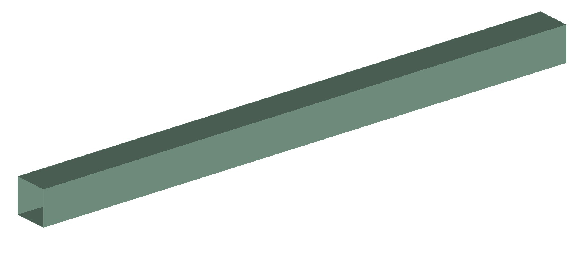
Figure 2: Culvert Modeling Tool Window within Wireless InSite window.
The next step is to define the transmitter and receivers that correspond to the system being modeled. In this case, the transmitter is at the entrance to the culvert and is defined as a half-wave dipole operating at 1.3GHz. The first receiver set is a vertical line of receivers extending from the floor to the ceiling of the culvert and running down the length of the culvert. The second receiver set is a horizontal line spanning the diameter of the culvert opening, and running down the length of the culvert at the height of the transmitter. The receiver sets are defined by isotropic antennas receiving at 1.3GHz. Figure 3 shows the location of the transmitter and receivers within the scene.
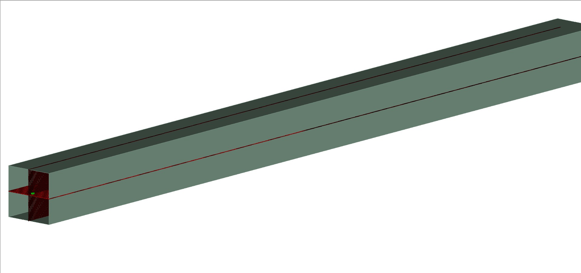
Figure 3: Transmitter and receiver locations within the Wireless InSite GUI.
With the transmitter and receivers placed, the next step is to define the bounds of the study area. This sets the limits of the calculation space within the software. In this particular case, the study area should be defined directly around the culvert. This will save time and memory when the calculation is performed because the area of interest is only in the culvert. Any area outside the culvert will be ignored. Figure 4 shows the study area around the culvert.
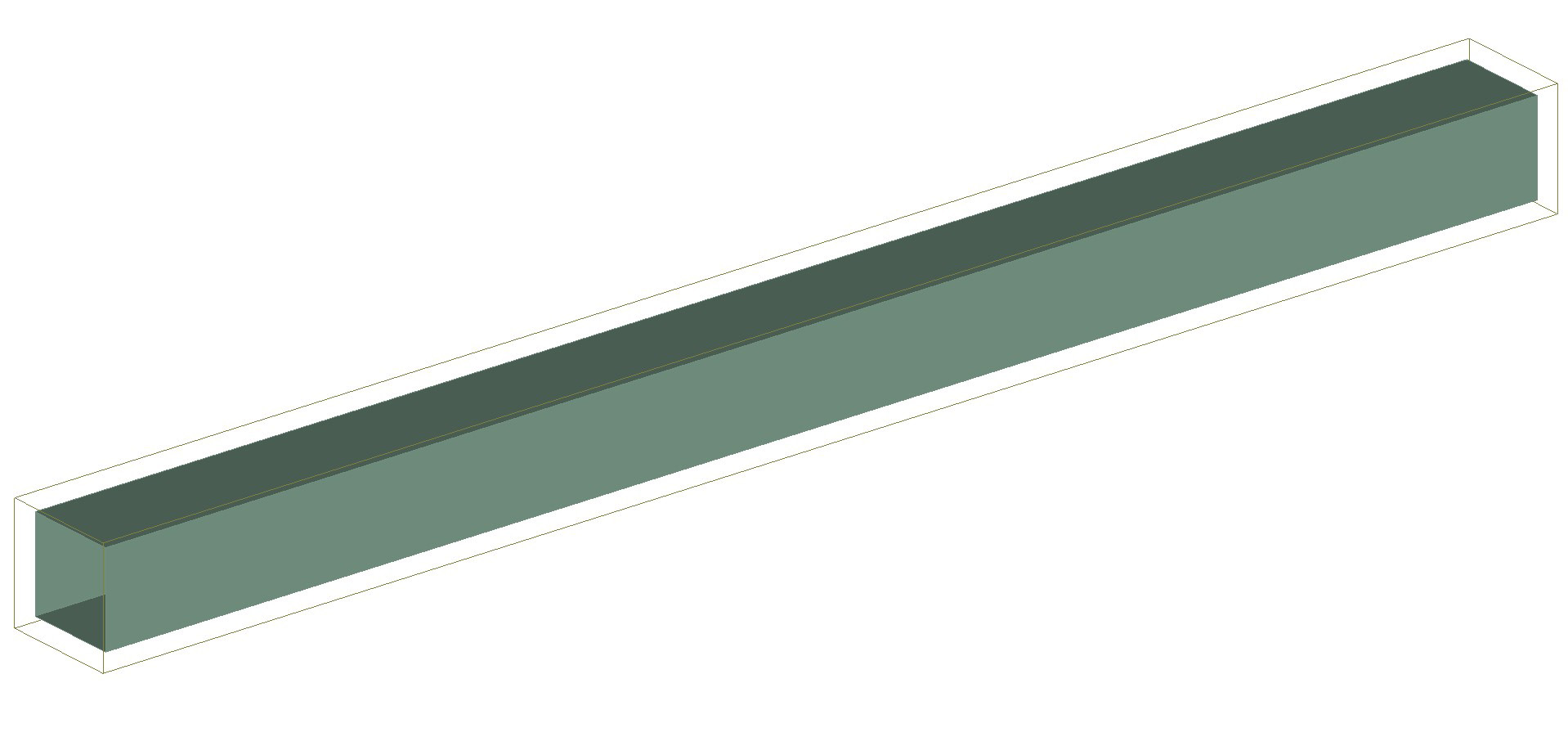
Figure 4: Study area bounds within Wireless InSite.
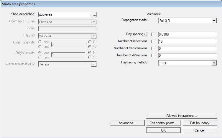
Figure 5: Study area properties window.
The propagation model is chosen within the study area properties menu as seen in Figure 5. In this case Full 3D was chosen. Full 3D is a Shooting and Bouncing Ray-tracing (SBR) model within Wireless InSite. The interactions were defined to be 16 reflections, 0 transmissions, and 0 diffractions. These limits tell the engine how many interactions a ray can encounter before it is no longer considered to be active. The ray spacing was set to 0.03 degrees which tells the engine how close together to shoot the rays. A higher density of rays in the scene results in a higher number of interactions between the rays and the faces in the scene, which theoretically results in higher accuracy in the results; however, there are a couple tradeoffs. The first tradeoff is that the more rays that are shot in the scene, the longer the run times become. The second tradeoff is that there is a point of diminishing returns where the results change very little with increasing ray set density. In most culvert examples, ray spacing with Full 3D can be set to 0.1 degrees. In this case, a denser grid was used to show the capabilities.
Once the calculation has been run, results can be examined to see how the system performs in the culvert. Figure 6 shows the received power from the vertical receiver set. Figure 7 shows the received power from the horizontal receiver set. The culvert acts almost like a waveguide in the results. There is constructive and destructive interference as seen in each figure. Figure 8 shows the vertical received power using a different viewpoint within the software.
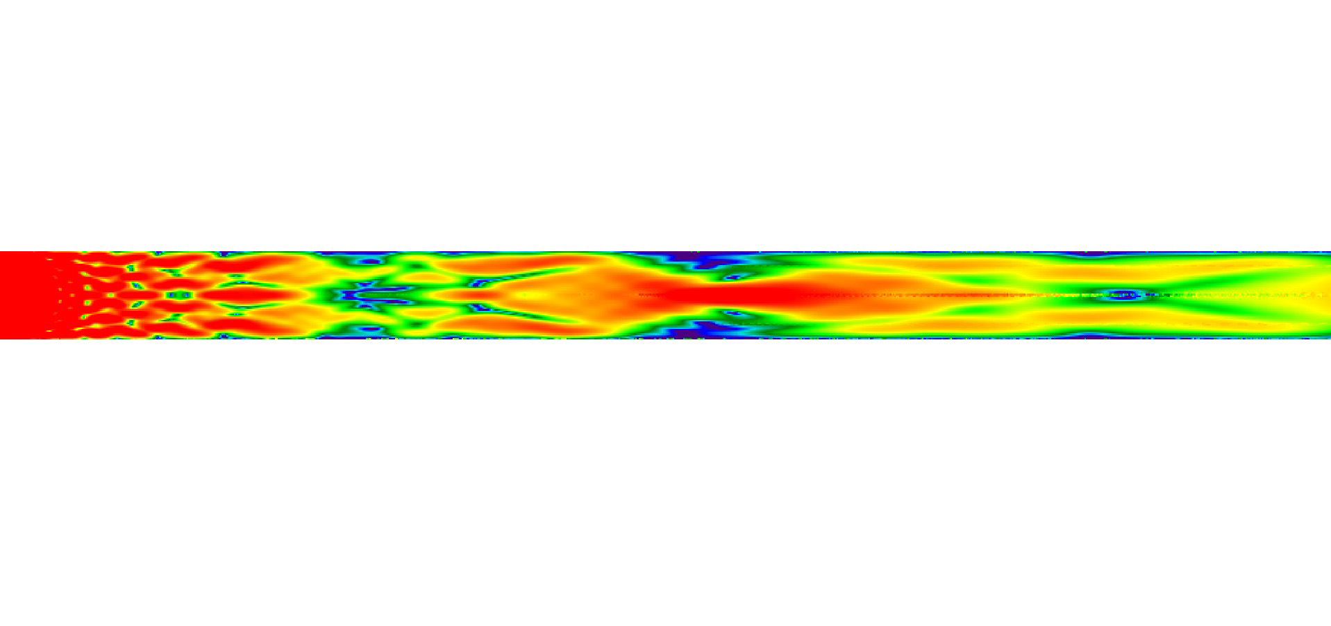
Figure 6: Received power for the vertical plane of receivers.
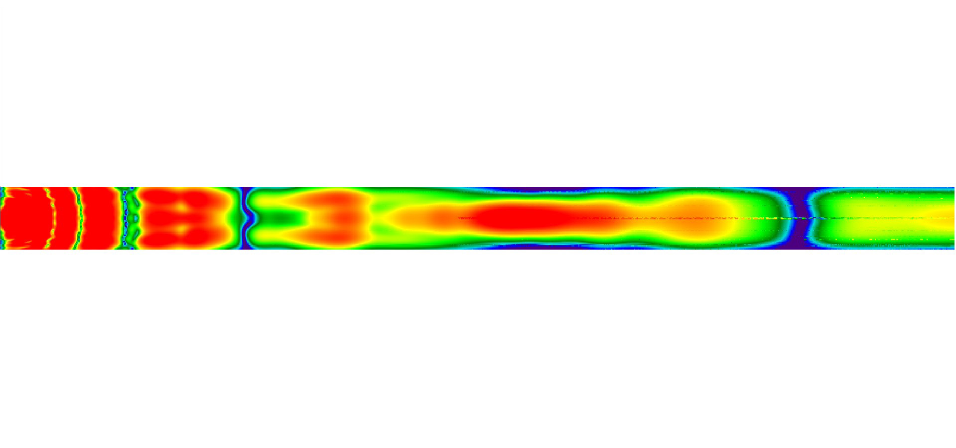
Figure 7: Received power for the horizontal plane of receivers.
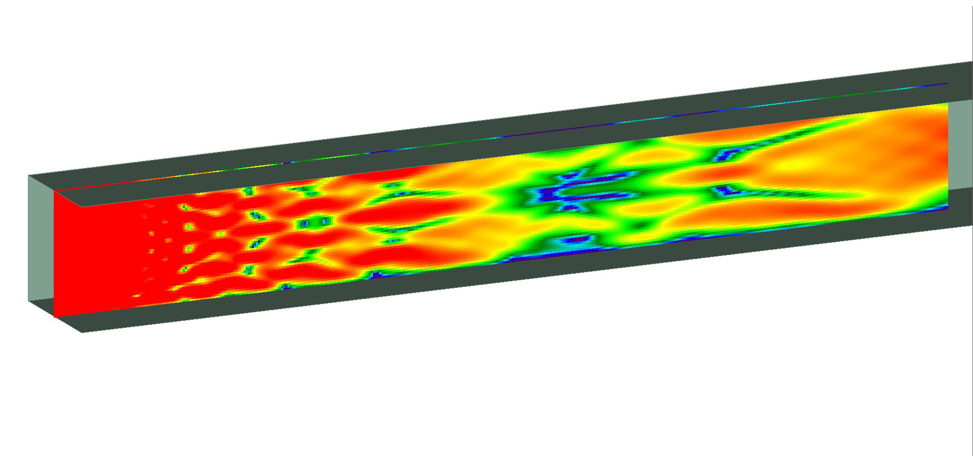
Figure 8: Received power for the vertical plane of receivers when looking into the culvert.
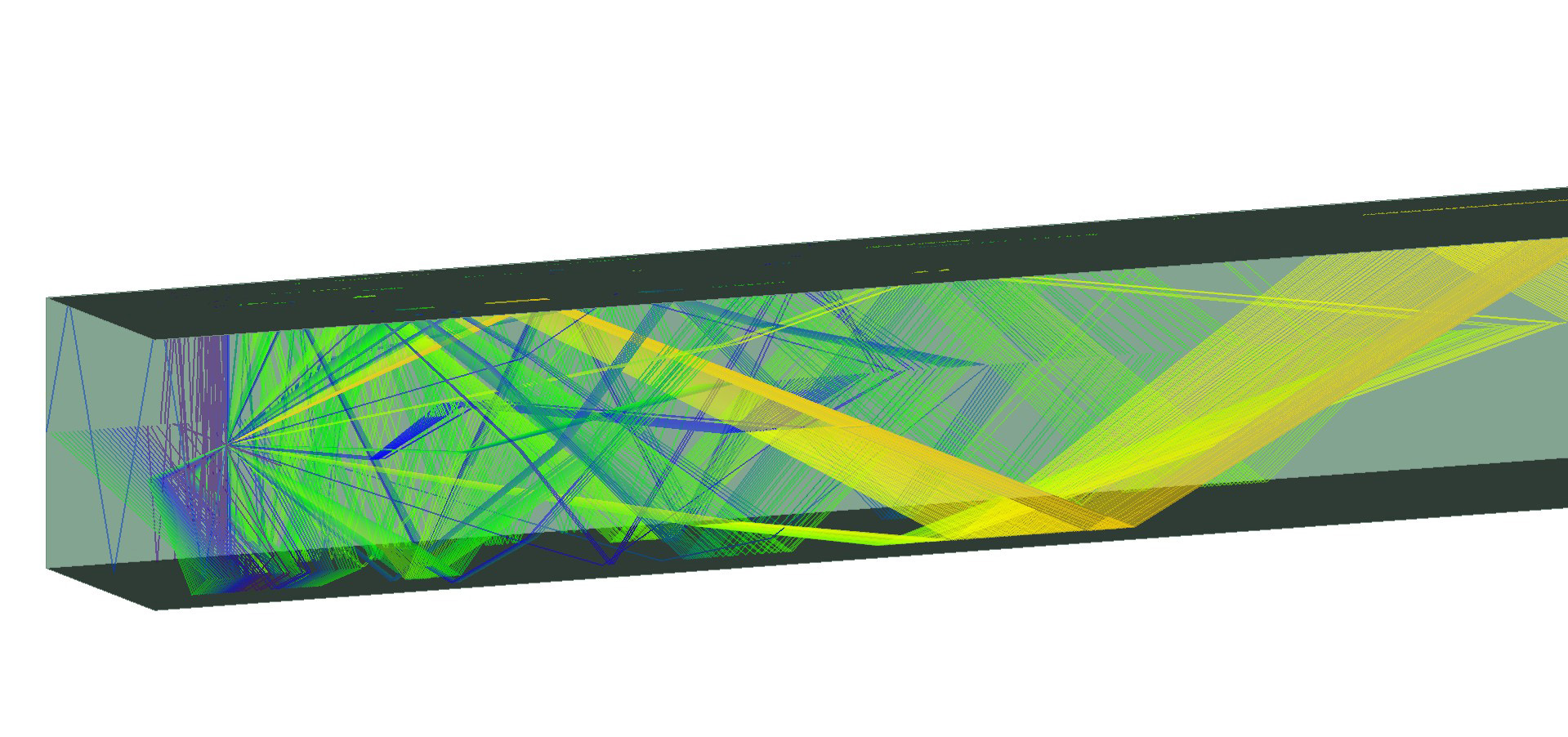
In addition to received power, the ray paths can be viewed. Figure 9 shows ray paths within the culvert.

Figure 9: Ray paths for the vertical plane of receivers.
Wireless InSite has the ability to create movies of the rays propagating throughout the space as seen in Video 1. EField can also be displayed in movie form. Video 1 shows the rays propagating through the culvert.
This Wireless Insite example shows the performance of a transmitter operating in a culvert environment. The results were examined in two different planes to show how the culverts affect the energy distribution from the transmitter. In addition, the ray paths were examined for different points along the receiver grids. Wireless InSite provides an efficient way to model culverts and other enclosed scenarios with accurate results. The next stage of work for this particular example could be to add more obstacles like bends, carts, etc. into the scene. In addition, changing the material makeup of the culvert would be an interesting area to explore. All of these can easily be done in the Wireless InSite software.
Reference
-
Jamie Knapil Infantolino, Adam J. Kuhlman, Manoja D. Weiss, and Randy L. Haupt; “Modeling RF Propagation in Mines Using Wireless InSite,” Applied Computational Electromagnetics Society Conference, Monterey, CA, March 24-March 29, 2013.