The project chosen comes from the paper "Low-Profile Equiangular Spiral Antenna Backed by an EBG Reflector" [1]. In this paper, an equiangular spiral antenna that should operate between 3 and 10 GHz is simulated first on its own, then over a series of reflector surfaces. The final design combines the benefits of a reflecting surface, to aid the gain and directivity of the antenna, with an electromagnetic band gap surface that allows for a much lower profile than over a traditional PEC reflector.
The spiral antenna design is shown in Figure 1 and is of the equiangular type. When XACT Accurate Cell Technology meshing is applied to the antenna (Figure 2), the FDTD grid conforms nicely to the antenna design resulting in a clean feed region and accurate simulation performance without the need for very small cell resolution.

Figure 1: CAD representation of the equiangular spiral antenna.
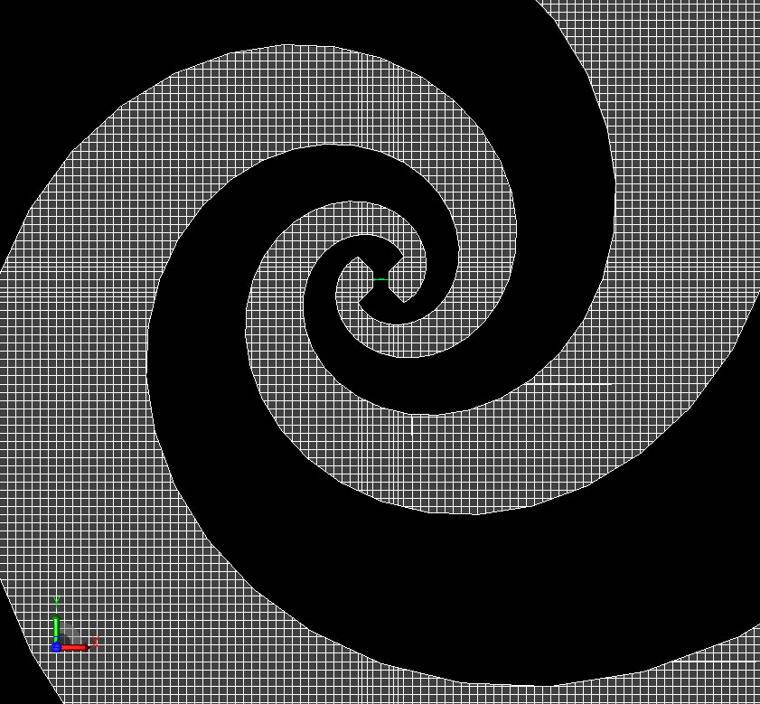
Figure 2: XACT mesh representation.
The antenna is simulated using a half-millimeter grid since the details of the EBG surface, to be added later, require a small grid spacing. A modulated Gaussian pulse voltage source is applied across the two arms of the spiral with a frequency content limited to the 3-10 GHz intended for this antenna. The input impedance of the spiral is nearly flat over the range of operation as expected (Figure 3). The axial ratio of the antenna is also quite flat over the frequency range and nearly one as shown in Figure 4.
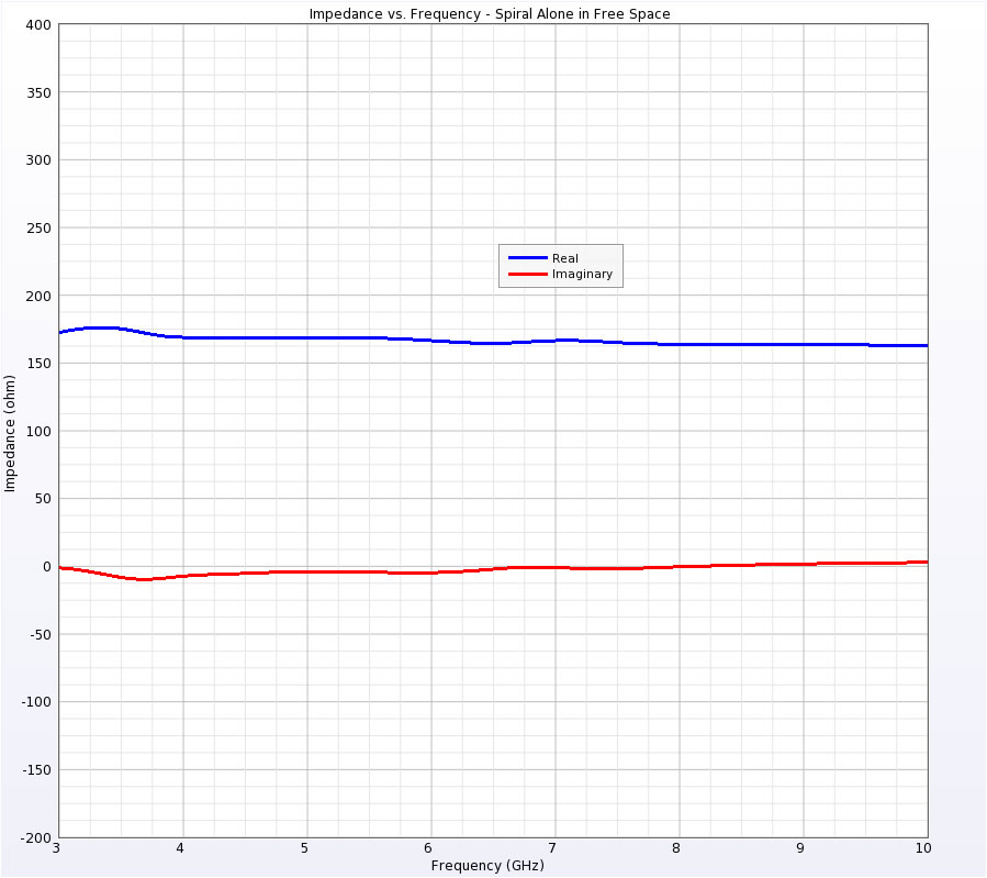
Figure 3: Impedance of antenna in free space.
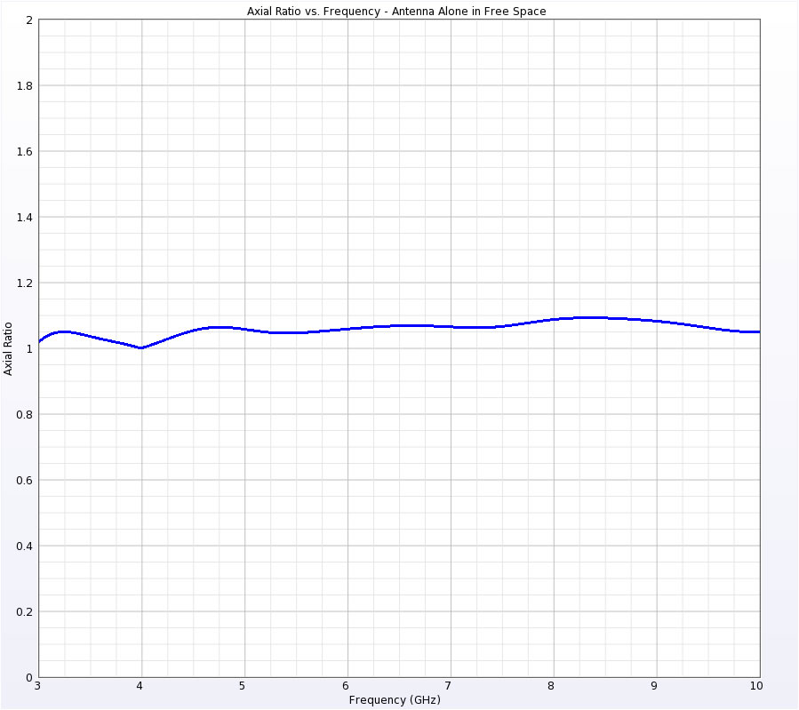
Figure 4: Axial ratio of antenna in free space
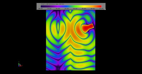
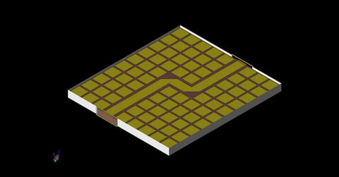
In practice the antenna will need to be mounted over some kind of reflector surface. Here the antenna is mounted above a modified EBG surface comprised of small patches connected to a ground plane through a dielectric substrate. Each patch is 13 x 13 mm with a small via spanning the 2 mm thickness of the substrate. The patches are 1 mm apart and the FDTD mesh of several patches is shown in Figure 5. The authors found that a configuration as shown in Figure 6 with the patches on the edges of the plane gave better performance than a surface filled with patches. This surface allows the antenna to be mounted just 7 mm above the EBG surface which is less than 1/10 of a wavelength at the lowest frequency. The performance of the antenna is quite good across the entire frequency range when placed above the modified EBG surface. The impedance is plotted in Figure 7 and is still relatively flat and compares well to the experimental results from the paper. The axial ratio in Figure 8 is quite reasonable and the peak gain above the spiral is also inline with the measurements (Figure 9).
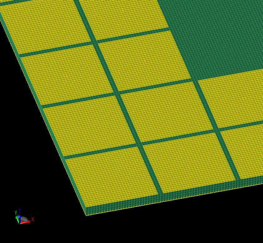
Figure 5: Mesh representation of EBG reflector.
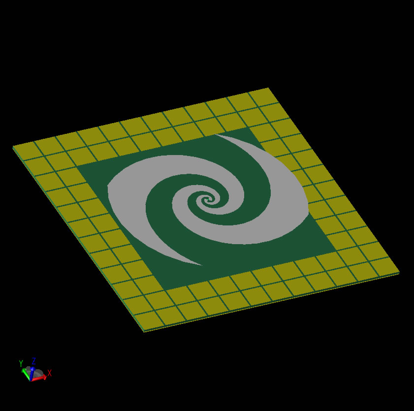
Figure 6: Full model with spiral antenna and EBG reflector.
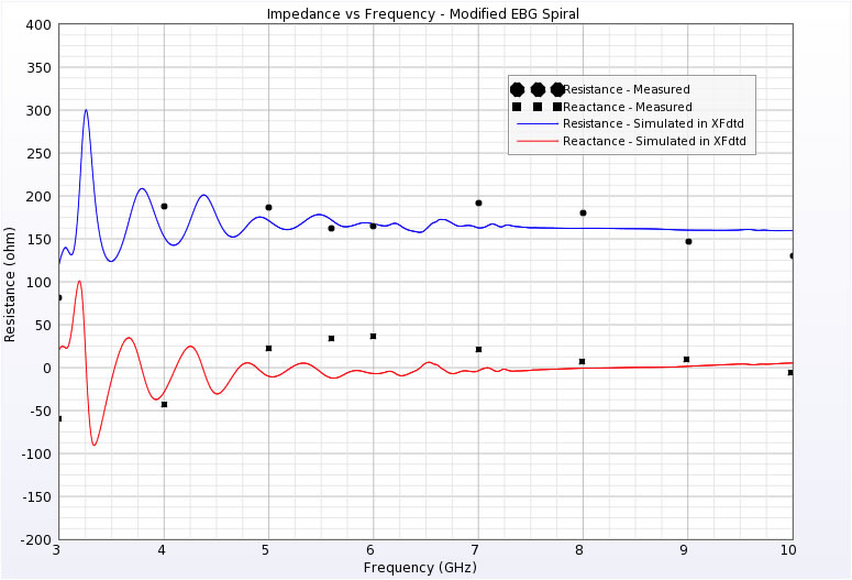
Figure 7: Comparison of impedance of antenna over EBG reflector.
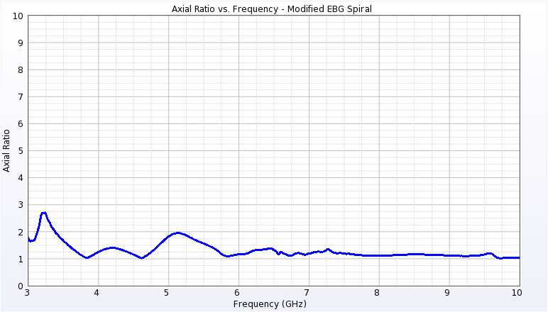
Figure 8: Axial ratio of antenna over EBG reflector.
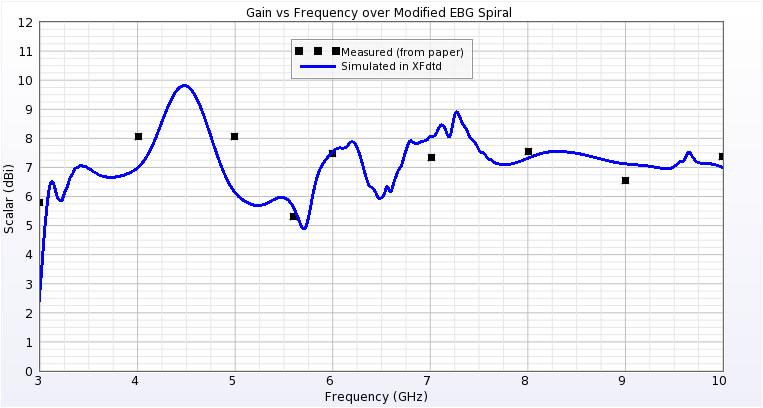
Figure 9: Comparison of peak gain of antenna over EBG reflector.
Reference
-
H. Nakano, K. Kikkawa, N. Kondo, Y. Iitsuka, and J. Yamauchi. "Low-Profile Equiangular Spiral Antenna Backed by an EBG Reflector." IEEE Transactions on Antennas and Propagation, vol. 57, no. 5, pp. 1309-1318, May 2009.